Great Planes Reactor Bipe 3D EP ARF - GPMA1580 User Manual
Page 21
21
GET THE MODEL READY TO FLY
Check the Control Directions
❏
1. Turn on the transmitter and receiver and center the
trims. If necessary, remove the servo arms from the servos
and reposition them so they are centered. Reinstall the
screws that hold on the servo arms.
❏
2. With the transmitter and receiver still on, check all the
control surfaces to see if they are centered. If necessary, adjust
the clevises on the pushrods to center the control surfaces.
❏
3. Make certain that the control surfaces and the throttle
respond in the correct direction as shown in the diagram.
If any of the controls respond in the wrong direction, use
the servo reversing in the transmitter to reverse the servos
connected to those controls. Be certain the control surfaces
have remained centered. Adjust if necessary.
Set the Control Throws
To ensure a successful fi rst fl ight, fl y your Reactor Bipe
set up only according to the C.G. and control surface
throws specifi ed in this manual. The throws and C.G. are
not arbitrary, but have been determined through extensive
testing and accurate record-keeping. This provides you
with the best chance for success and enjoyable fi rst fl ights
that should be surprise-free. Additionally, the throws and
C.G. shown are true, real data which will allow the model to
perform in the manner in which it was intended when fl own
by a pilot of the skill level for which it was intended. DO
NOT OVERLOOK THESE IMPORTANT PROCEDURES.
A model that is not properly set up may be unstable and
possibly unfl yable.
❏
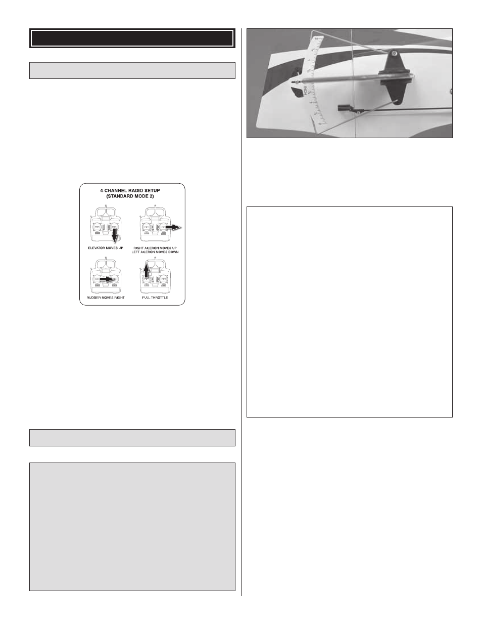
Use a Great Planes AccuThrow (or a ruler) to accurately
measure and set the control throw of each control surface as
indicated in the chart that follows. If your radio does not have
dual rates, we recommend setting the throws at the low rate
setting. Note: The throws are measured at the widest part
of the elevators, rudder and ailerons.
These are the recommended control surface throws:
High Rate
Low Rate
ELEVATOR:
9/16" [14mm] up
5/16" [8mm] up
9/16" [14mm] down 5/16" [8mm] down
RUDDER:
2-1/4" [57mm] right 1-3/16" [30mm] right
2-1/4" [57mm] left
1-3/16" [30mm] left
AILERONS:
3/4" [20mm] up
3/8" [10mm] up
3/4" [20mm] down 3/8" [10mm] down
3D RATES
3D ELEVATOR 1-1/4" [30mm] up
1-1/4" [30mm] down
3D RUDDER 3-3/8" [87mm] right
3-3/8" [87mm] left
3D AILERONS 1-1/8" [28mm] up
1-1/8" [28mm] down