Channel radio setup – Great Planes Gee Bee Profile 40 Kit - GPMA0485 User Manual
Page 21
U 11. Install the Screw-Lock Pushrod Connector in the
throttle servo arm. Slide the throttle pushrod through the
pushrod connector. With the radio switched on, adjust the
throttle trim to high. Move the throttle stick to full throttle
and move the throttle arm on the carburetor to full open.
Tighten the 4-40 set screw in the pushrod connector.
Check the movement of the throttle. The carburetor should
not close completely when the throttle stick is moved to low.
The carburetor should close completely only when the
throttle trim is moved to low.
D 2. Or, the covering can be cut from over the cockpit
opening. Cut the drawing of the pilot bust from the plan
sheet and glue it to a leftover piece of plywood. Trim the
plywood to the outline of the bust. Felt tip markers or paint
can be used to color the bust. Stick a pin in the bottom of
the bust and cut the end of the pin off. Insert the bust in the
cockpit and glue in place. Clear MonoKote or thin butyrate
can be placed over the cockpit to simulate windows.
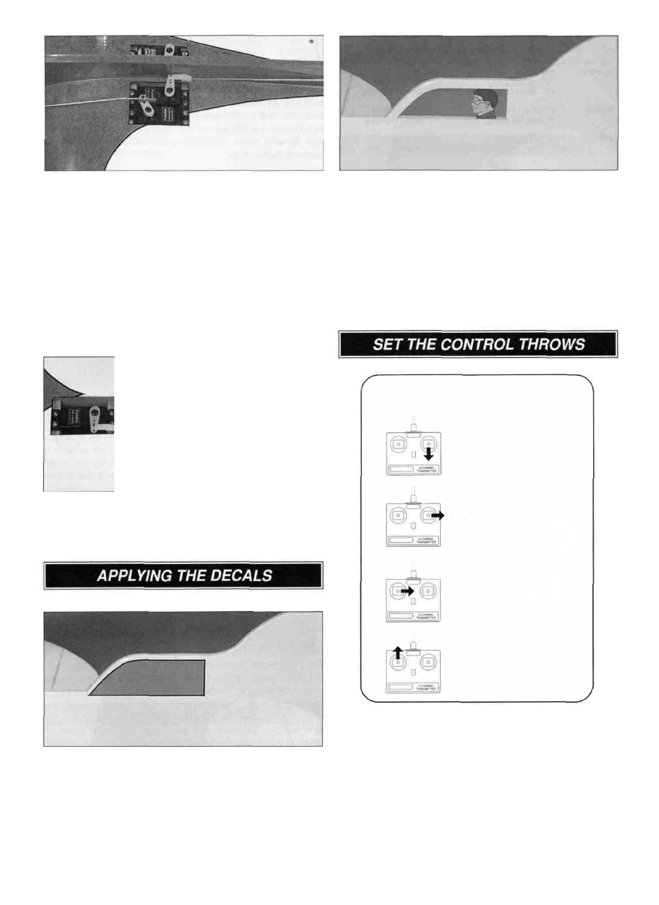
4-CHANNEL RADIO SETUP
(STANDARD MODE 2)
ELEVATOR MOVES UP
RIGHT AILERON MOVES UP
LEFT AILERON MOVES DOWN
RUDDER MOVES RIGHT
NOSE WHEEL TURNS RIGHT
CARBURETOR WIDE OPEN
D 12. Install the 12" aileron pushrods following the same
procedure used to install the elevator pushrod.
D 1. The cockpit can be finished in two different styles. If
you left the sheeting over the cockpit area, the canopy
decal can be cut from the decal sheet and placed over
the cockpit area.
The throws are measured at the widest part of the
elevators, rudder and ailerons. Adjust the position of the
pushrods at the servo horns to control the amount of throw.
You may also use the ATV'S if your transmitter has them but
the mechanical linkages should still be set so the ATV'S are
near 100% for the best servo resolution (smoothest, most
proportional movement).
21