Great Planes Gee Bee Profile 40 Kit - GPMA0485 User Manual
Page 20
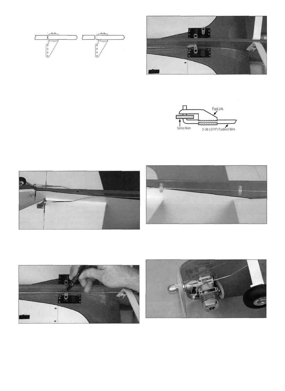
RIGHT WRONG
D 4. Position the large control horn on the elevator and the
small control horn on the rudder. Align the horns with the
hinge line, as shown in the sketch and the plan. Mark the
location of the mounting holes and drill a 3/32" hole at the
marks. Mount the control horns on the e l e v a t o r and
rudder with the backing plate and 2-56 x 1/2" screws.
D 5. Mark the location on both sides of the fuse for the
nylon pushrod guides. Refer to the fuse plan for the
proper location. NOTE: The guides on the left side are off-
set from the guides on the right side.
D 8. Make a 90° bend at the marks you made. Cut the
pushrods 3/8" above the bend and connect the pushrods to
the servos with nylon faslinks.
NOTE: If necessary, enlarge the holes in the servo arms
with a 5/64" drill bit (or a #48 drill bit for precision).
D 6. Bend both pushrods so that they are positioned next
to the fuse sides. Make sure the bends are aft of the aft
pushrod guide location.
D 9. Position the nylon pushrod guides on the sides of
the fuse, at the marks made in step 5. Mark the location of
the guide mounting holes and drill a 1/16" hole at each
mark. Attach the guides to the fuse sides with #2 x 3/8"
sheet metal screws.
D 7. With the radio switched on and the servos centered,
position the elevator and rudder to neutral. Mark the
pushrods where they cross the mounting holes in the
servo arms.
D 10. Slide a silicone retainer over the threaded end of a
12" threaded pushrod. Thread a nylon clevis 14 turns
onto the pushrod. Bend and cut the pushrod to fit your
engine installation, making sure that the muffler does not
interfere with the pushrod.
20