Great Planes Gee Bee Profile 40 Kit - GPMA0485 User Manual
Page 16
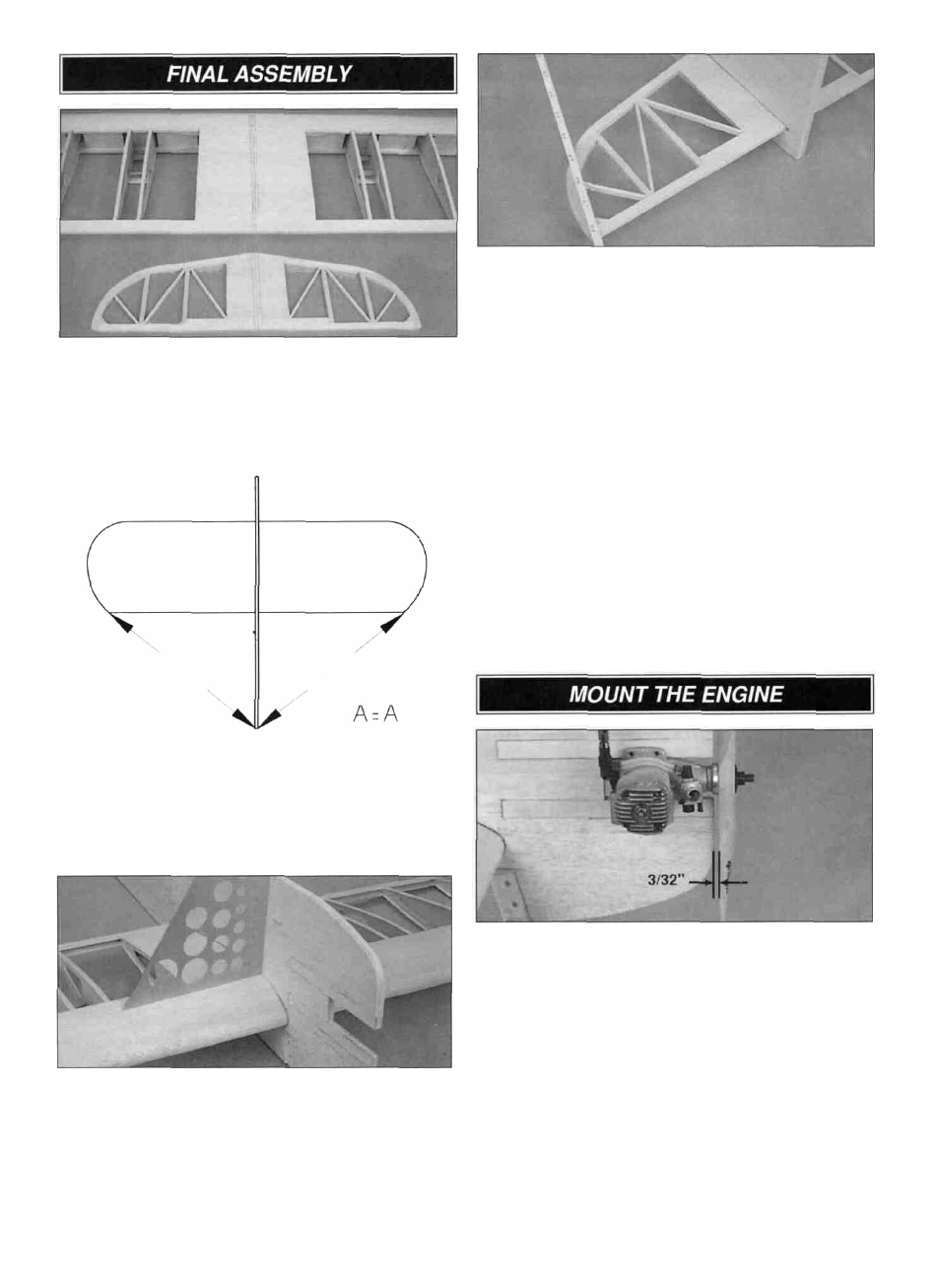
D 1. Draw a centerline from leading edge to trailing edge
on the top of the wing and stab. Draw a parallel line 3/16"
on each side of the centerlines. Insert the wing in the fuse.
A
A
D 2, Carefully center the wing in the fuse. Check that the
wing tips measure the same distance from the center of the
tail and that the wing is perpendicular to the fuse sides.
I—I 3. Use 30-minute epoxy to glue the wing to the fuse.
Check that the wing is centered and perpendicular to the
fuse. After the epoxy has cured, fill any gaps with
microballoons and epoxy.
D 4. Center the stab in the stab slot using the centerline
you drew in step #1. View the airplane from the aft end. If
the stab tips are not an equal distance above the wing,
carefully sand the high side of the stab slot until the stab is
aligned. With the stab positioned at the forward end of the
stab slot, check that the stab tips measure the same
distance from the center of the nose.
D 5. Use 30-minute epoxy to glue the stab to the fuse.
After the epoxy has cured, fill any gaps with a mixture of
microballoons and epoxy.
D 6. Position the rudder on the TE of the fuse and mark
the hinge and tailgear bearing locations. Carefully cut hinge
and tailgear bearing slots in the TE of the fuse. Test fit the
rudder on the fuse.
D 7. Attach the landing gear to the fuse using two 6-32 x
3/4" cap head screws, two #6 washers and two 6-32
lock nuts.
D1 1. Install a propeller on your engine. Center the engine
between the engine rails with the back of the propeller
approximately 3/32" from the front of the fuselage.
D 2. Mark the engine mounting holes on the engine rails.
Drill four 1/8" holes through the engine rails at the marks.
D 3. Use two #4 washers under the two front holes
between the engine and the rails. This will provide the 2
degrees of right thrust required. Secure the engine to the
rails with four 4-40 x 1" pan head bolts, 4-40 locknuts
and #4 washers.
16