Great Planes Gee Bee Profile 40 Kit - GPMA0485 User Manual
Page 17
Do not confuse this procedure with "checking the C.G." that
will be discussed later in the manual
Now that the model is nearly completed, you should
balance it laterally (side-to-side) An airplane that is laterally
balanced will track better during acrobatic maneuvers
Here's how
1 Temporarily attach the elevators, rudder, engine and
landing gear Lift the model by the propeller shaft and the
bottom of the fuse near the rudder. This will require an
assistant Do this several times
Cover the model with Top Flite MonoKote film, using the
suggested covering sequence that follows Before you
cover the fuselage first apply 1/4" wide strips of MonoKote
film in the corners where the stab and wing meet the
fuselage Proceed to cover the stab with pre-cut pieces that
meet in the corners and overlap the 1/4" strips Never cut
the covering on the stab and fin after it has been applied
except around the leading and trailing edges and the tips
Modelers who do this may cut through the covering and
into the stab This will weaken the structure to a point
where it may fail during flight.
2 The wing that consistently drops indicates the heavy
side Balance the model by adding weight to the opposite
wing tip.
Some modelers prefer to cover the top and bottom of the
ailerons with one strip of MonoKote film This is done by
covering the bottom first, then wrapping the MonoKote film
up over the leading edge
We used Top Flite MonoKote White (TOPQ0204), Missile
Red (TOPQ0218) and Black (TOPQ0208) to cover our
Gee Bee Profile
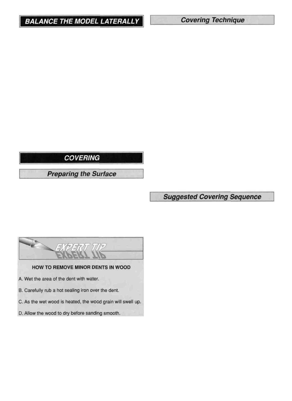
D 1 Remove the engine, landing gear and any other
hardware you may have installed.
D 2 Most of the model should be rough-sanded by now,
with all edges sanded and rounded following the cross-
section views on the plans Fill all dents, seams, low spots
and notches with HobbyLite" balsa colored filler
D 3 After the filler has dried use progressively finer
grades of sandpaper to even and smooth all the edges,
seams and surfaces Remove all the balsa dust from the
model with compressed air or a vacuum with a brush and a
tack cloth
Fuselage and Tail:
1. 1/4" strips at the stab and wing as described
2. Fuselage right side (use the "balsa template' made
on page 15 to cut out the wing opening)
3. Fuselage left side (Use the template here also)
4. Fin TE, followed by stab TE
5. Stab bottom, followed by top
6. Rudder Leading Edge
7. Rudder, followed by the left side
8. Elevator LE
9. Elevator bottoms, followed by the top
Wing:
1. T E of wing
2. Bottom right, followed by the left wing panel
3. Top right, followed by the left wing panel
4. Aileron LE, followed by the bottom and top
17