GME TX3520W User Manual
Page 32
PA G E 3 2 I n s t r u c t I o n m A n uA l
t X 3 5 1 0 s / t X 3 5 2 0 s / t X 3 5 4 0 s
t X 3 5 1 0 s / t X 3 5 2 0 s / t X 3 5 4 0 s
I n s t r u c t I o n m A n uA l
PA G E 3 3
CHANNEL
PRIORITY
SQL LVL
PUSH
PUSH
Plastic tab
3. Gently press the rubber strain relief into the hole
surrounding the socket so that the slot around the strain
relief fi ts neatly inside the lip of the hole.
rear
1. the rear microphone cover hinges from the top. simply
lift the cover from the bottom. the cover will remain
connected to the chassis.
2. Position the microphone plug so the plastic tab faces
downwards, and press the plug into the socket until
it ‘clicks’.
lift microphone
cover
Plastic tab
removing the Microphone
1. For front panel connections, fi rst squeeze the rubber strain
relief near the front panel to disengage the slot, and slide
the strain relief back along the microphone cord.
2. For both connections, squeeze the plastic tab on the
microphone plug towards the plug to unlock it while
gently pulling the plug outwards. If the plug does not
come out easily, the tab has not released correctly and
should be squeezed again.
Fitting the Controller Microphone
Plug the 8 pin plug into the socket on the front of the main
unit or alternatively you can use the adapter and extension
cable supplied with the radio. If the main unit is not easily
accessible this adapter will allow you to bring the microphone
socket to a more convenient position
Attach the microphone clip to a convenient location near your
driving position using screws. slide the bollard on the back of
the microphone into the clip to secure it.
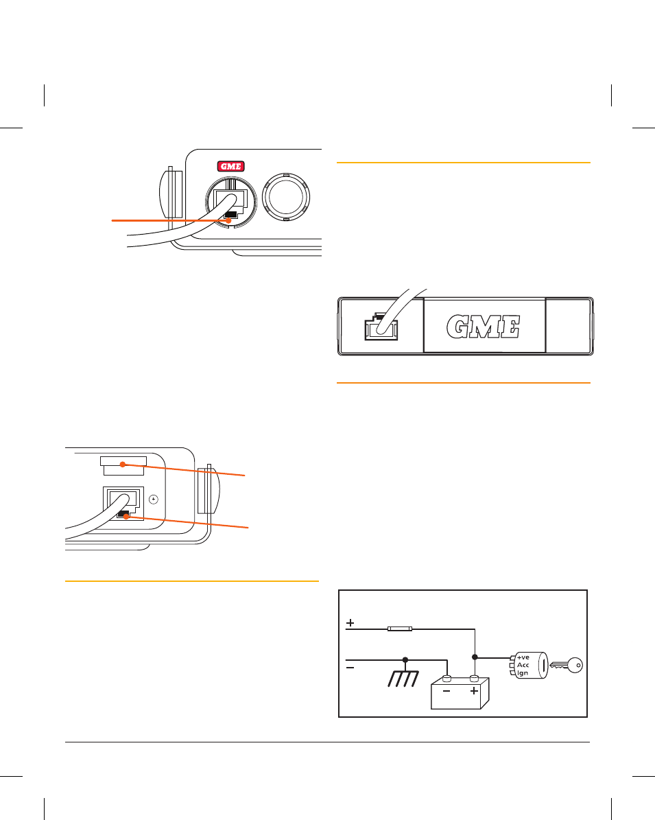
DC POwEr CONNECtION
the radio is designed for 13.8 volt Dc, negative earth
installations only (i.e. where the negative terminal of the
battery is connected to the chassis or frame of the vehicle).
there are two recommended methods of installation.
radio remains ON when the ignition switch is OFF
connect the radio’s negative (black) lead to the vehicle’s
chassis, or if preferred, directly to the battery’s negative
terminal. the radio’s positive (red) lead should be connected
via the 2 amp fuse to the battery’s positive terminal.
Alternatively, the positive lead could be connected into
the fuse box at a point that has +13.8 volts continuously
available (on the battery side of the ignition switch) via the
2 amp fuse.
Radio remains ON when ignition switch is OFF
RED
Fuse
Fuse
BLACK
Chassis
Car battery
Ingnition Switch
Radio turns ON and OFF with ignition switch
RED
BLACK
Chassis
Car battery
Ingnition Switch
To Radio
To Radio
radio turns ON and OFF with the ignition switch
connect the radio’s negative (black) lead to the vehicle’s
chassis, or if preferred, directly to the battery’s negative
terminal. the radio’s positive (red) lead should connect to an
accessory point in the vehicle’s fuse box via the 2 amp fuse.
this point should supply +13.8 volts only when the ignition
switch is turned on or in the AccEssorY position via the 2
amp fuse.
Radio remains ON when ignition switch is OFF
RED
Fuse
Fuse
BLACK
Chassis
Car battery
Ingnition Switch
Radio turns ON and OFF with ignition switch
RED
BLACK
Chassis
Car battery
Ingnition Switch
To Radio
To Radio
High Voltage Detection
the radio has a built-in, high voltage detection system to
warn you if an overvoltage situation occurs. If the power
supply voltage exceeds 18 volts Dc, the channel display will
fl ash ‘hi dc’ for 5 seconds when the unit is fi rst turned on, or
at the time the voltage exceeds 18 volts. In addition, when
transmitting, the tX indicator will fl ash and the transmitter
will select low output power.
If the overvoltage warning appears you should switch your
radio oFF and disconnect it from the power source, before
locating the cause of the trouble.
once the ‘High Voltage’ warning has been triggered, and you
have fi xed the source of the problem, you will need to switch
the radio oFF then on again to reset it.
NOTE:
the power source should never exceed 30 volts.