Governor basic map. 1 2 – Futaba CGY750 User Manual
Page 16
16
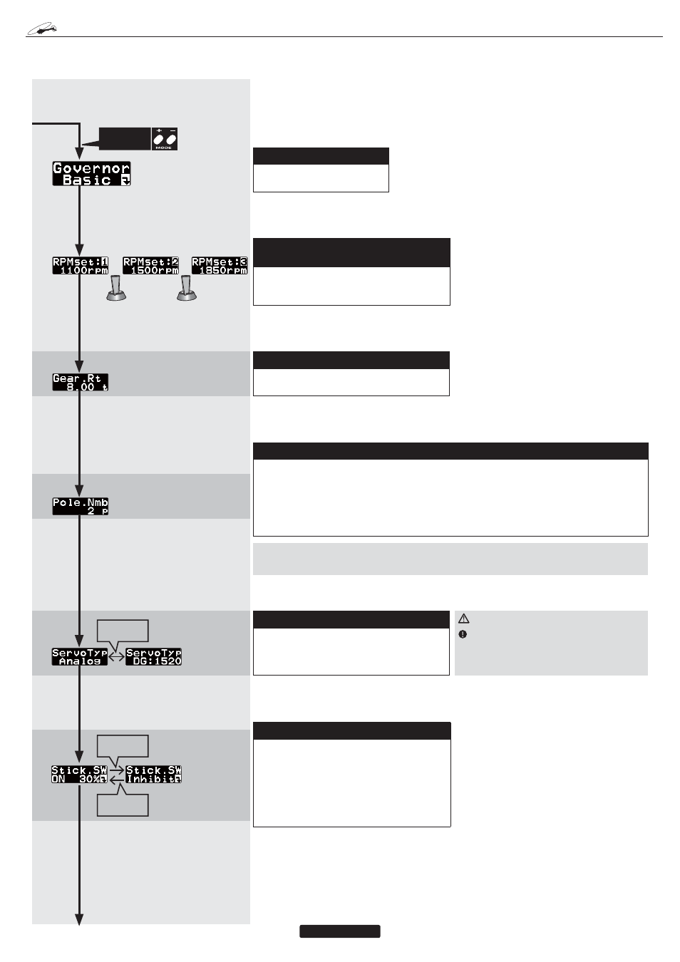
(1) Start display
The editing menus are scrolled
by pushing the mode + or – key.
(2) Revolution setting [range: 700
4000
rpm]
Setting the main rotor revolution. This is calcu-
lated by engine revolution with the gear ratio of
the main shaft.
(3) Gear ratio [default: 8.00, range: 1 50]
Input the main rotor gear ratio by pushing the
data + or-key.
G
OVERNOR
B
ASIC
S
ETTING
*It does not display, when Opr.mode is
Gyro+THR, and when SWASH-type is
H4-00/H4-45.
*It does not display, when Opr.mode is
Gyro+THR, and when SWASH-type is
H4-00/H4-45.
*It does not display, when Opr.
mode is Gyro+THR, and when
SWASH-type is H4-00/H4-45.
*It does not display, when Opr.
mode is Gyro+THR, and when
SWASH-type is H4-00/H4-45.
7KLVPHQXVHWVWKHJRYHUQRU¶VIXQGDPHQWDOIXQFWLRQV7KHPHQXServo
limit point settingPXVWEHVHW¿UVW
(5) Servo selection [default: Analog]
Select the throttle servo type. Digital servos of-
fer the best response. The type is changed by
pushing data + or – key.
(6) Stick switch [default: 30%]
The governor can be activated by throttle stick
position. Move the throttle stick to the desired
governor on position and push SET key, memo-
rizing that point. When you push the RSET key,
the function is inhibited. When the governor on/
off switch is inhibited, the stick switch is auto-
matically turned on.
(4) Pole number [default: 2p, range: 2p 24p]
This function sets the motor pole count. This function is used when employing a direct phase
sensor attachment to a brushless motor lead. Input the motor pole count as specified by the
brushless motor manufacturer. When using any revolution sensor other than a direct phase sen-
sor type, set the pole number to 2p.
NOTE: The input signal range of the CGY750 is 0.0v-3.0v. Exceeding this voltage range may
cause damage to the CGY750.
GOVERNOR BASIC
MAP. 1 2
WARNING
This parameter must match the type of
servo you are using. Incorrect setting may
damage the CGY750 or the servo, possibly
resulting in a loss of control during flight.
****Please see the Governor EXPERT menu in the ADVANCED TUNING SECTION at
the end of this manual for additional guidelines for governor use with electric models.
Push
DATA
+/– key
Push
DATA
– key
Push
DATA
+ key
Push
MODE
+/– key