Futaba 9VHP User Manual
Page 3
Setting Method
• Make the basic linkage settings according to the
helicopter manufacturer's instructions, except
allow for slightly more total collective pitch
travel than specified.
6) Move the cursor to the HI (High Pitch) setting
the desired low pitch limit by pressing the
program key (usually
about 0 or-1 ).
position with the
cursor key.
•Select the MIX screen and then press the
(PITCH) program key. Select the CURVE
program by pressing the
(CURVE) pro-
gram key.
• Move the cursor to the top left corner of the
screen and select the curve that you wish to set
by pressing the
program key.
NOTE: The ID1, ID2,
and HLD pitch curves
cannot be set until the corresponding Throttle
functions are activated (See pages 40 through 42).
Move the T/C stick to the full High position,
and set the High Pitch Trim Lever on the right
side of the transmitter to the center position.
Measure the actual pitch on the model with a
guage, and set the desired High Pitch limit
with the
program key.
•The High Pitch setting can be trimmed con-
veniently during flight by using the High Pitch
Trim Lever. A maximum adjustment of ±25%
is possible. Sensitivity of the trim lever can be
adjusted by moving the cursor to the LEVER
•The setting method is the same for the NOR,
ID1, ID2, and HLD curves and is described
below.
1) Select the NORMAL curve setting screen as
described above.
2) Move the cursor to the INH position with the
cursor key and activate the NORMAL
pitch curve by pressing the
program key.
3) Switch the airborne system ON and set the
T/C stick on the transmitter to the center
(hover) position.
4) Adjust the model linkage to give the desired
pitch at hover (use a pitch gage to measure).
5) Move the cursor to the LO (Low Pitch) posi-
tion with the
cursor key. Move
position and using the
pro-
gram key. The High Pitch Trim Lever also
adjusts the High Pitch in the ID1 and ID2
modes. NOR, ID1, and ID2 limits can be set
separately.
• The low pitch limit in the NORMAL mode can
be adjusted ±25% with the NOR OI.LO. sub-
trimmer on the trimmer panel.
•Sub-trimmers are also available for IDL UP2
PI. LO., HOLD PI. HI., HOLD PI. LO., and
IDL UP1 PI. LO. When a trimmer is turned
slowly, a buzzer will sound at the center or
neutral (sub-trim = 0) position. The pitch rate
actually set (including the sub-trim amount) is
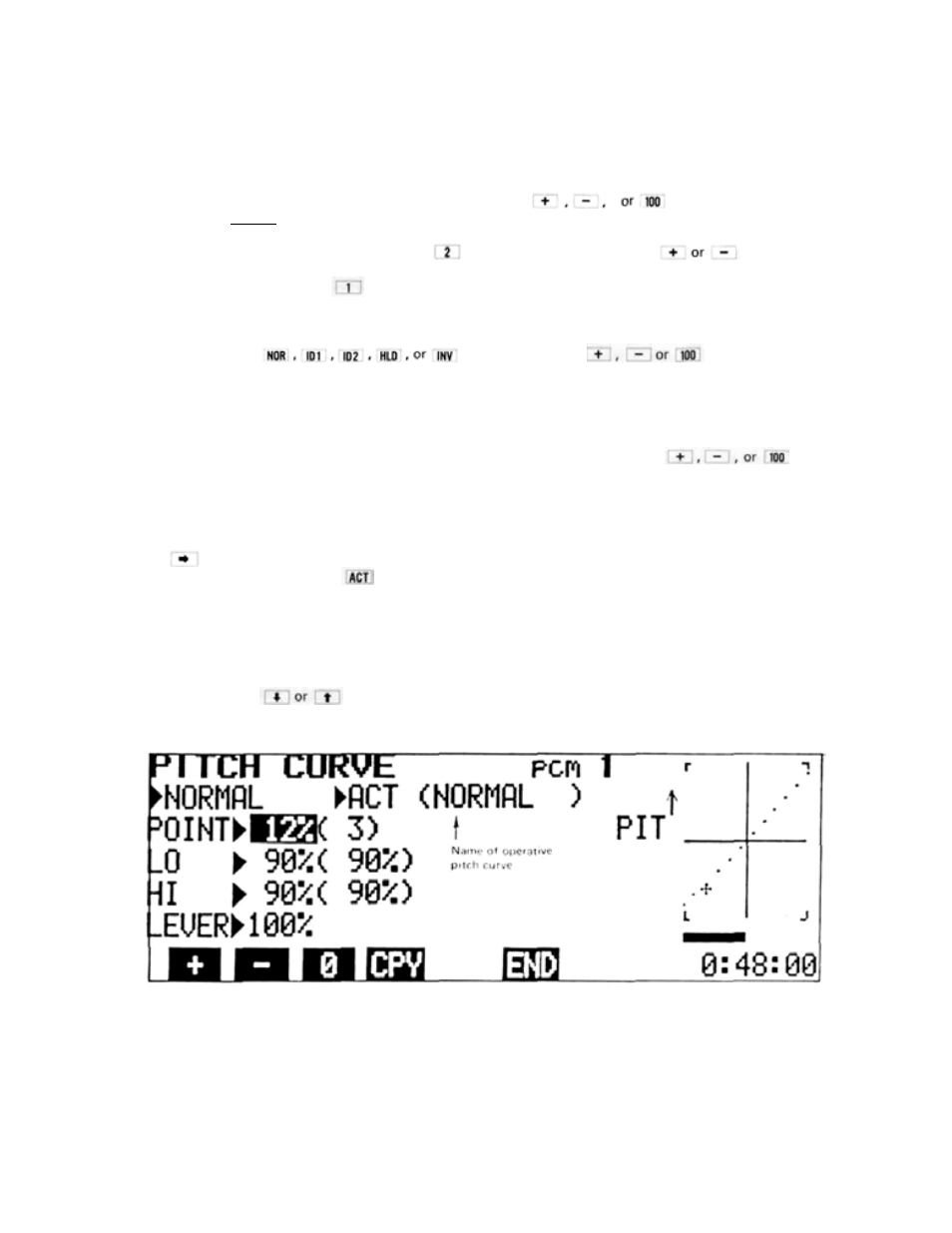
displayed in ( ) on the screen.
the T/C stick to the full low position, and set
Pitch Curve Point Setting Method
• Once the basic settings are made, the curve can
be further refined utilizing the Point Cursor in
conjunction with the curve display graph on
the right side of the screen.
• The pitch curve displayed on the graph is divid-
ed into 11 equal parts. There are 12 individual
dots or "points" that represent the curve on
the graphic display. Each of these points can
be individually adjusted UP or DOWN using
the "Point Cursor".