Components – FloAire Indirect Fired Heater User Manual
Page 19
19
Components
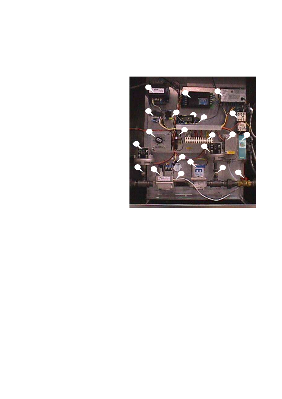
The following image and list outlines the typical in-direct fired heater components and their functions.
1. Power Transformer – Installed
when motor voltage > 120V. Used
to provide 120V service to controls.
2. Control
Transformer
–
120V
primary; 24V secondary control
transformer.
3. Discharge Temperature Set-Point
–
Controls
the
discharge
air
temperature. Furnace will not light if
air temperature is higher than set-
point.
4. Low
Gas
Pressure
Switch
(Optional) – De-energizes furnace
controls if gas pressure falls below
its set-point.
5. Inlet Gas Pressure Tap – Inlet gas
pressure should be measured here.
6. Combination
Gas
Valve - A
combination of redundant solenoid
valves, pilot valve and gas regulator
built into one unit.
7. Power Vent Relay – Energizes
power vent motor on call for heat.
8. Maxitrol Modulating Amplifier -
Regulates
temperature
by
modulating gas valve
9. Freeze-Stat Thermostat (Optional) – De-energizes blower motor if the discharge air
temperature falls below the set point.
10. Circuit Breaker – Protects electrical components from high current spikes.
11. Burner View Port – Allows burner to be monitored.
12. Pilot Tubing – Pilot tube connection to combination gas valve.
13. Automatic Reset Thermal Limit – Safety device that prevents the furnace from overheating.
14. Modulating Gas Valve – Modulates gas flow to burner to provide proper air temperature.
15. High Gas Pressure Switch (Optional) – De-energizes furnace controls if gas pressure rises
above its set-point.
16. Terminal Strip – Central location to terminate control wiring. Should be used for troubleshooting.
17. Flame Safety Control – Initiates and monitors flame.
18. Motor Starter – Contactor with overload protection to start and protect motor.
19. Airflow Switch – A safety device insuring proper air flow during furnace operation.
20. Manifold Gas Pressure Tap – Manifold gas pressure should be measured here.
21. Manual Gas Shut-Off Valve Allows gas flow to burner to be shut off to leak test gas train
22. Intake Thermostat – Used on Models with two furnaces. Cycles second (downstream) furnace
on and off with fluctuations in intake air temperature. Should be set to [Temp Discharge set point
minus temp rise of first heat exchanger plus 5 degrees F)
1
4
3
2
8
17
18
5
21
10
11
20
19
12
7
9
15
6
14
16
13
22