Sequence of operation, Maxitrol amplifier pulley combination chart, Modulating gas system – FloAire Indirect Fired Heater User Manual
Page 16
16
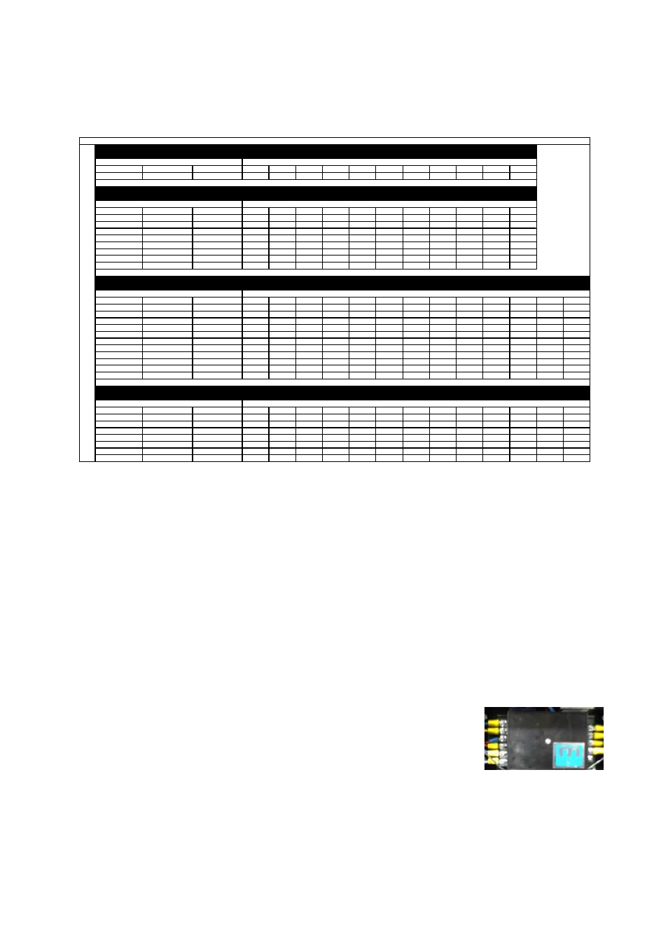
Maxitrol Amplifier
Pulley Combination Chart
Motor RPM
1725
1/3 to 1-1/2 HP
MOTOR PULLEY
Dd1
Dd2
Pd1
Pd2
AX BELTS
1VL34
1.9
2.9
2
3
Open
Closed
BLOWER PULLEY
DATUM DIAMETER
PITCH DIAMETER
5
4 1/2
4
3 1/2
3
2 1/2
2
1 1/2
1
1/2
0
AK114
11
11.2
308
323
339
354
370
385
400
416
431
447
462
1/3 to 2 HP
MOTOR PULLEY
Dd1
Dd2
Pd1
Pd2
AX BELTS
1VL40
2.4
3.4
2.6
3.6
Open
Closed
BLOWER PULLEY
DATUM DIAMETER
PITCH DIAMETER
5
4 1/2
4
3 1/2
3
2 1/2
2
1 1/2
1
1/2
0
AK114
11
11.2
400
416
431
447
462
477
493
508
524
539
554
AK94
9
9.2
488
506
525
544
563
581
600
619
638
656
675
AK79
7.5
7.7
582
605
627
650
672
694
717
739
762
784
806
AK66
6.2
6.4
701
728
755
782
809
836
863
889
916
943
970
AK54
5
5.2
863
896
929
962
995
1028
1062
1095
1128
1161
1194
AK46
4.2
4.4
1019
1059
1098
1137
1176
1215
1255
1294
1333
1372
1411
AK39
3.5
3.7
1212
1259
1305
1352
1399
1445
1492
1539
1585
1632
1678
AK32
3
3.2
1402
1455
1509
1563
1617
1671
1725
1779
1833
1887
1941
3 to 5 HP
MOTOR PULLEY
Dd1
Dd2
Pd1
Pd2
BX BELTS
2VP42
2.9
3.9
3
4
Open
Closed
BLOWER PULLEY
DATUM DIAMETER
PITCH DIAMETER
6
5 1/2
5
4 1/2
4
3 1/2
3
2 1/2
2
1 1/2
1
1/2
0
2BK160H
15.4
15.7
330
339
348
357
366
375
385
394
403
412
421
430
439
2BK140H
13.4
13.7
378
388
399
409
420
430
441
451
462
472
483
493
504
2BK120H
11.4
11.7
442
455
467
479
491
504
516
528
541
553
565
577
590
2BK110H
10.4
10.7
484
497
511
524
537
551
564
578
591
605
618
631
645
2BK100H
9.4
9.7
534
548
563
578
593
608
622
637
652
667
682
697
711
2BK90H
8.4
8.7
595
611
628
644
661
677
694
710
727
744
760
777
793
2BK80H
7.4
7.7
672
691
709
728
747
765
784
803
821
840
859
877
896
2BK70H
6.4
6.7
772
794
815
837
858
880
901
923
944
965
987
1008
1030
2BK60H
5.4
5.7
908
933
958
984
1009
1034
1059
1084
1110
1135
1160
1185
1211
2BK55H
4.9
5.2
995
1023
1050
1078
1106
1133
1161
1189
1216
1244
1272
1299
1327
2BK50H
4.4
4.7
1101
1132
1162
1193
1223
1254
1285
1315
1346
1376
1407
1438
1468
7-1/2 to 10 HP
MOTOR PULLEY
Dd1
Dd2
Pd1
Pd2
BX BELTS
2VP60
4.3
5.5
4.7
5.9
Open
Closed
BLOWER PULLEY
DATUM DIAMETER
PITCH DIAMETER
6
5 1/2
5
4 1/2
4
3 1/2
3
2 1/2
2
1 1/2
1
1/2
0
2BK160H
15.4
15.7
516
527
538
549
560
571
582
593
604
615
626
637
648
2BK140H
13.4
13.7
592
604
617
630
642
655
667
680
693
705
718
730
743
2BK120H
11.4
11.7
693
708
722
737
752
767
781
796
811
826
840
855
870
2BK110H
10.4
10.7
758
774
790
806
822
838
854
871
887
903
919
935
951
2BK100H
9.4
9.7
836
854
871
889
907
925
943
960
978
996
1014
1031
1049
2BK90H
8.4
8.7
932
952
972
991
1011
1031
1051
1071
1091
1110
1130
1150
1170
2BK80H
7.4
7.7
1053
1075
1098
1120
1143
1165
1187
1210
1232
1255
1277
1299
1322
TURNS ON MOTOR PULLEY
TURNS ON MOTOR PULLEY
1
0
-
1
8
I
N
.
B
L
O
W
E
R
TURNS ON MOTOR PULLEY
TURNS ON MOTOR PULLEY
Sequence of Operation
The Indirect-fired heater is most easily understood when broken down into smaller individual systems.
There are two main systems, a make-up air fan and a heater. The make-up air fan consists of a heavy-
duty blower and motor. The heater may be further broken down into two control systems, the Flame
Safety Control (FSC) and the Modulating Gas System (MGS). The burner mixes air with the gas (Natural
or Propane) which heats a heat exchanger which heats the air.
Modulating Gas System
The first system, the Maxitrol modulating gas system, consists of a
temperature selector dial, a discharge air sensor, an amplifier, and a modulating
gas valve. The two types of Maxitrol systems found on these units are the
Maxitrol 20/30 and the Maxitrol 21/31. The 20 and 21 series are for single
furnace arrangement and the 30 and 31 series are for multiple furnace
arrangement. The Maxitrol 21/31 utilizes a discharge air sensor and modulates
the discharge air to the selected temperature on the temperature selector dial.
The Maxitrol 20/30 utilizes a room temperature sensor/selector in order to
control the room temperature. The modulating gas valve controls the amount of gas to the burner based
on the temperature rise needed. When the modulating gas valve is all the way open and achieving the
maximum BTUs and temperature rise of the unit, it is called “high fire”.