FloAire Indirect Fired Heater User Manual
Page 12
12
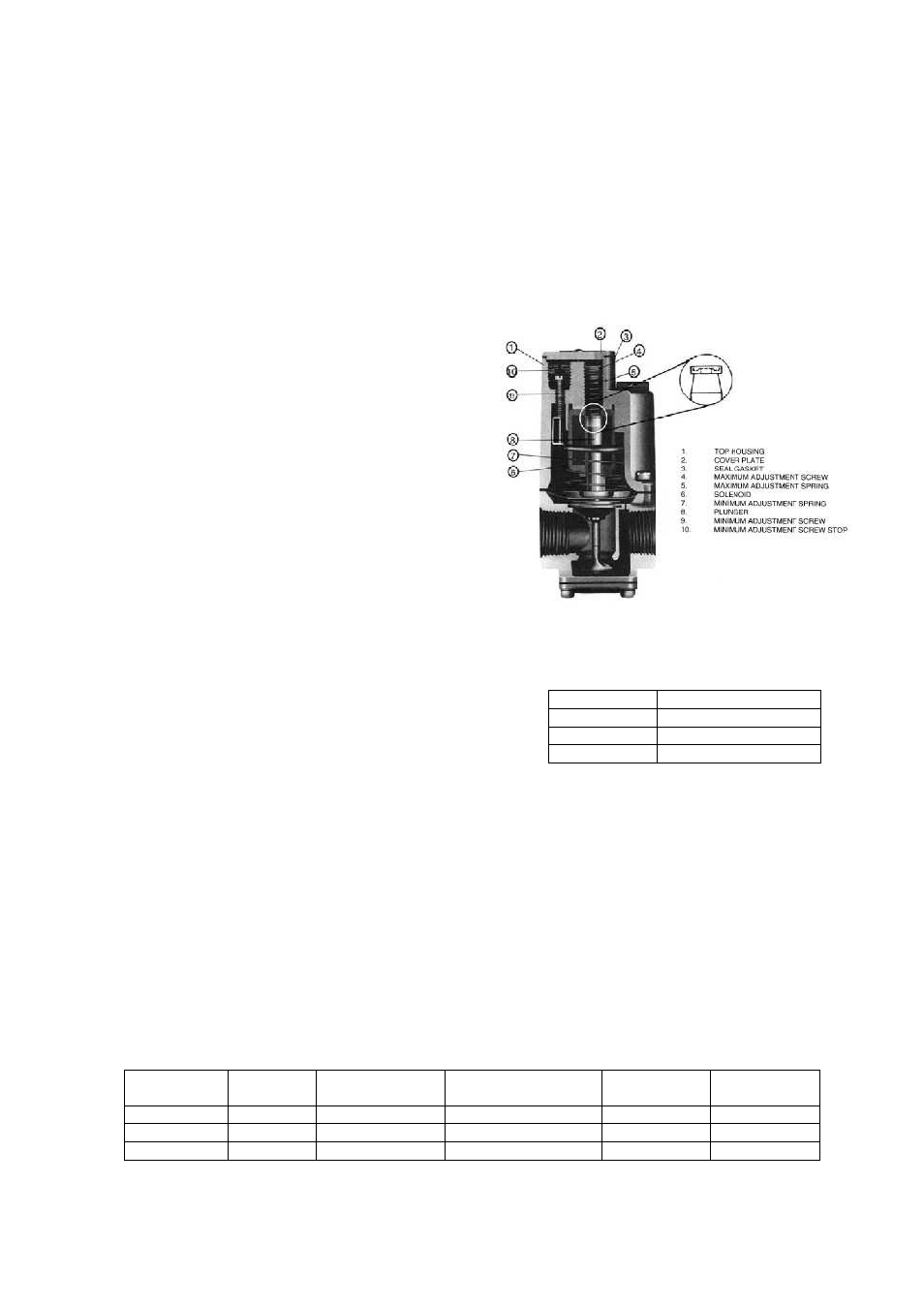
Maxitrol Modulating Valve
Orifice and Gas Consumption Chart
Furnace
Size
No. of
Orifices
Natural Gas
Orifice Drill Size
Propane Gas Orifice
Drill Size
Natural Gas
CFH
Propane Gas
CFH
200
3
23
40
192.3
80
350
6
27
43
336.5
140
400
6
23
40
384.6
160
Mod Valve Voltage Summary
Volts DC
Firing Mode
0 to 2 VDC
High Fire
2 to 14 VDC
Modulation
14 to 20 VDC
Low Fire
Main Burner Adjustment
1. Once the pilot has been properly established, the manifold gas pressure should be adjusted to
jobsite conditions. The gas pressure regulator (integral to the combination gas control) is
adjusted at the factory for average gas conditions. It is important that the gas be supplied to the
furnace in accordance with the input rating on
the rating plate.
2. Create a high fire call for heat. This should be
done with the blower on and all gas controls
on. High fire can be achieved by removing the
wire at terminal #3 from the Maxitrol amplifier
(0 VDC to modulating valve).
3. The manifold pressure should be checked at
the
pressure
tap
downstream
of
the
modulating valve. For natural gas systems,
the high fire manifold pressure should be set
at 3.5 in. w.c. For propane gas, the high fire
manifold pressure should be set to 10 in. w.c.
4. Remove the cap of the modulating valve.
Using the maximum adjustment screw, adjust
the high fire manifold pressure to 3.5 in. w.c.
for natural gas and 10 in. w.c. for propane gas.
If the high fire screw is at the end of its
adjustment and more pressure is needed, then
adjust the main gas pressure regulator spring
(on the combination valve) to achieve the
proper manifold pressure. Turning the
regulator screw clockwise will increase pressure and
counter-clockwise will decrease pressure.
5. Reconnect the wire on the Maxitrol amplifier at terminal
#3.
6. The low fire manifold pressure must now be set. This
is done by first moving the wire from terminal #11 on
the Maxitrol amplifier to terminal #10. The temperature
set-point should be set to its minimum set-point. Place
a jumper wire between terminal #3 and terminal #4 on the Maxitrol amplifier.
7. Using the minimum adjusting screw, adjust low the low fire manifold pressure to 0.56 in. w.c. for
natural gas and 1.6 in. w.c. for propane gas. Replace the cap to the Maxitrol valve and restore
all of the original wiring on the Maxitrol amplifier and gas components.
8. The main burner flame can be viewed after loosening and pushing aside the gas designation disc
on the side of the burner box. The appearance of the flame can be adjusted by changing the
manifold air shutters. To increase primary air, loosen the air shutter set screws and move the air
shutters closer to the manifold. To decrease primary air, move the air shutters away from the
manifolds. Retighten set screws after adjustment. Proper operation provides a soft blue flame
with a well-defined inner core. A lack of primary air will produce soft, yellow tipped flames.
Excess primary air produces short, well-defined flames with a tendency to lift off the burner ports.
9. A final gas leak check shall be performed to verify the gas-tightness of the heater’s components
and piping under normal operating conditions.