Chapter 3 • connection – syncing m-kadex, Installation, Guide – FingerTec m-Kadex Manual User Manual
Page 6: Communication, Diagrams, Description of available connections, Ingress online activation, Installation and setup of ingress, Connecting terminals to ingress, Using usb to download/upload data
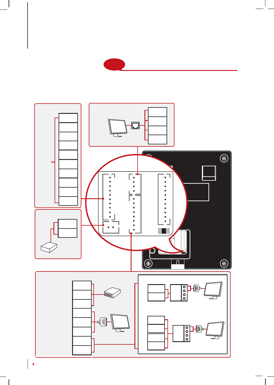
J7
AL-
AL+
NC
COM
NO
BUT
GND
SES
BELL+
BELL-
J2
RJ45-1
RJ45-2
RJ45-3
RJ45-6
J12
WDO
WD1
GND
RXD
TXD
GND
485A
485B
GND
+12V
V3.6 - 09032
J1
J7
AL-
AL+
NC
COM
NO
BUT
GND
SES
BELL+
BELL-
J2
RJ45-1
RJ45-2
RJ45-3
RJ45-6
J12
WDO
WD1
GND
RXD
TXD
GND
485A
485B
GND
+12V
V3.6 - 09032
J1
Back of Terminal
NOTE
The installation guides is for installer reference only
For NC
or NO
door
lock
system
AL-
AL+
NC
COM
NO
BUT
GND
SES
BELL+
BELL-
ACCESS CONNECTION
PORT
DC12V
Power Supply
GND
+12V
TCP/IP PORT
(Ethernet Connection)
-
TCP/IP
RJ45-1
RJ45-2
RJ45-3
RJ45-6
3rd party controller
with 26 bits wiegand
input
RS232
cable
1. RS485 Single Connection
2. RS485 Network Connection
RX+
RX-
485A
485B
485A
485B
RS232/RS485 Data
Converter
WD0
WD1
GND
RXD
TXD
GND
485A
485B
Wiegand Output
RS232
RS485
RS232/RS485/WIEGAND CONNECTION PORT
POWER SUPPLY
PORT
RX+
RX-
RS232/RS485 Data
Converter
485A
485B
3 •
CONNECTION – SYNCING M-KADEX
Installation Guide
Communication Diagrams
At the rear of every terminal, there are connections available for power, communica-
tion and door access. Refer to the following diagrams for the terminals you require.