Digilent Minicon User Manual
Page 8
Digilent, Inc.
Minicon Reference Manual
www.digilentinc.com
www.digilentinc.com
page 8 of 8
Copyright Digilent, Inc. All rights reserved. Other product and company names mentioned may be trademarks of their respective owners.
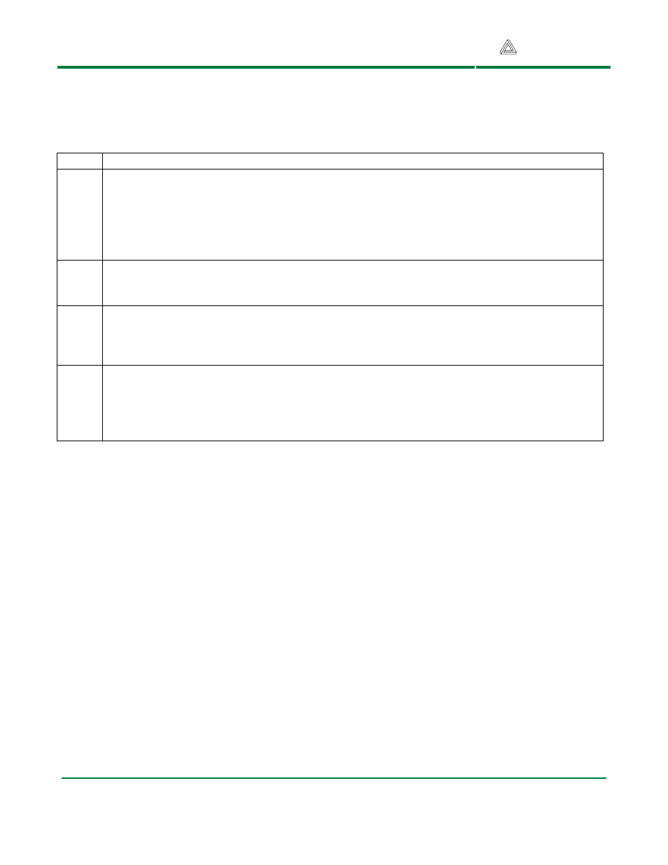
Table 2: Jumper Block Settings
Jumper Function
JP1-4 6-pin Pmod headers
Any of the five 6-pin Pmod headers can use either regulated or unregulated power. To use
regulated power place the jumper block over the center pin and the pin marked VCC. To use
unregulated power, place the jumper block over the center pin and the pin marked VU. SPI
connector J1 and RS232 connector J2 share jumper block JP1.
JP5-6
User input jumpers
JP5 is connected to port B, pin 6. JP6 is connected to port B, pin 7.
JP7-8 User input jumpers
These jumpers are connected through a voltage divider to analog input ADC6.
JP9
Power supply selection
With a shorting block in the VU position, external power is routed through the on-board
voltage regulator. With a shorting block in the VCC position, external power bypasses the
on-board voltage regulator.