Digilent Minicon User Manual
Page 7
Digilent, Inc.
Minicon Reference Manual
www.digilentinc.com
www.digilentinc.com
page 7 of 8
Copyright Digilent, Inc. All rights reserved. Other product and company names mentioned may be trademarks of their respective owners.
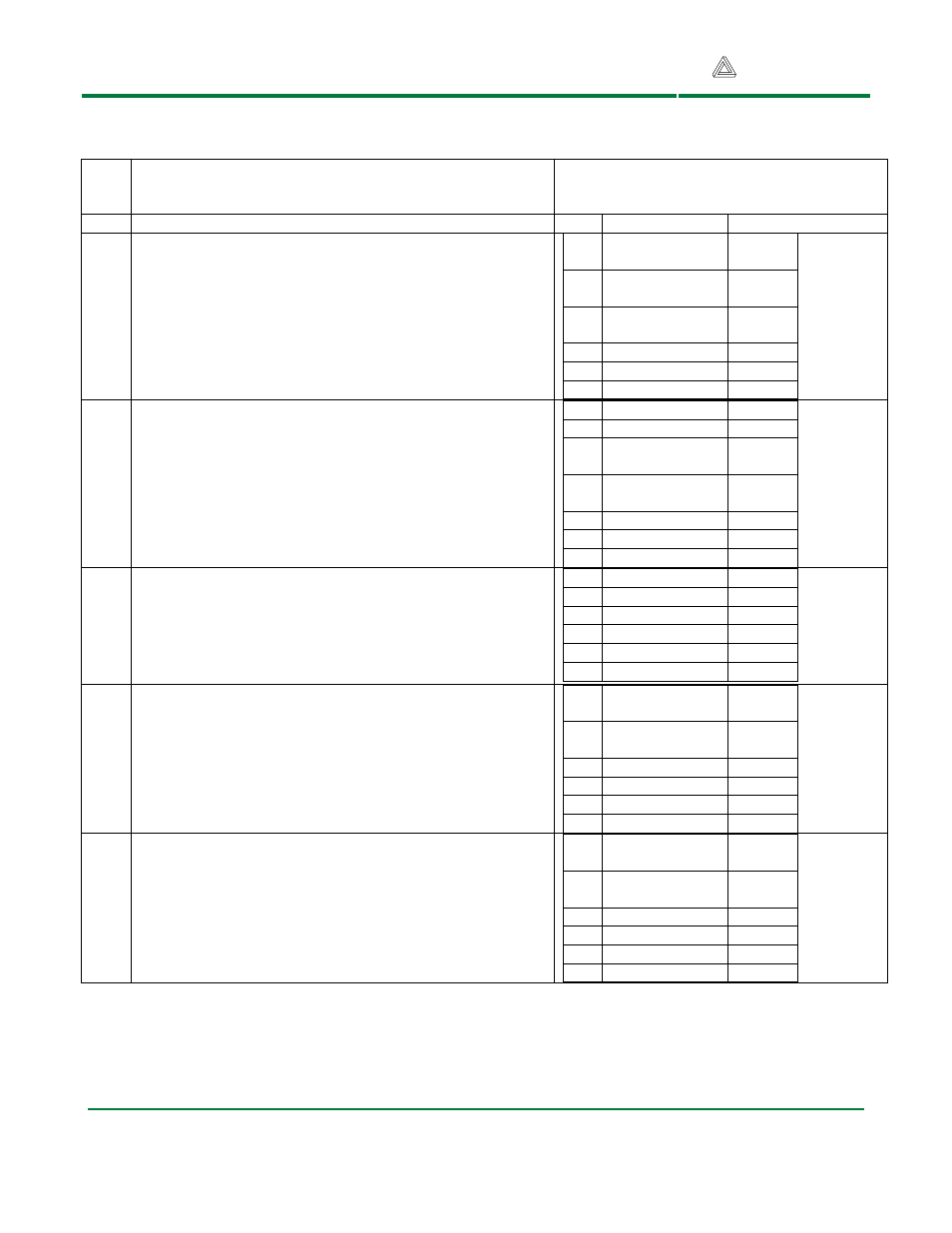
Table 1: 6-pin PMOD headers and SPI
connection
Pin
Description: All Pmod connector pins can be used for
general purpose I/Os. The following descriptions are for use
with specific Digilent Pmod modules:
Minicon Pmod header pins to ATmega168
ports/bit
Pin
Function
Port/bit
JA
General purpose I/Os and on board LEDs
1
PCINT20/XCK/
T0
PD4
2
PCINT21/OC0B/
T1
PD5
3
PCINT22/OC0A
/AIN0
PD6
4
PCINT23/AIN1
PD7
5
GND
6
VCC
JB
H-bridge connection
This connector is for use with an H-bridge module. Pins 1 and 2
are the direction and enable signals for the H-bridge. Pins 3 and
4 are for encoder feedback.
1
INT0/PCINT18
PD2
2
PCINT1/OC1A
PB1
3
PCINT0/CLKO/I
PC1
PB0
4
PCINT19/OC2B/
INT1
PD3
5
GND
6
VCC
JC
Analog input
This connector provides inputs to the analog to digital converter
of the ATmega168.
1
ADC0/PCINT8
PC0
2
ADC1/PCINT9
PC1
3
ADC2/PCINT10
PC2
4
ADC3/PCINT11
PC3
5
GND
6
VCC
J1
SPI interface and in-system-programming
The SPI interface is accessed on J1 when the shorting block is in
the SS position on JP10. Connector J1 is used for in-system-
programming when the shorting block on JP10 is in the RST
position.
1
PCINT2/SS/OC1
B
PB2
2
PCINT3/OC2A/
MOSI
PB3
3
PCINT4/MISO
PB4
4
SCK/PCINT5
PB5
5
GND
6
VCC
J2
Serial port communications and interrupts
The USART serial port and the ATMEL TWI interface can be
accessed on J2.
1
ADC5/SCL/PCI
NT13
PC5
2
ADC4/SDA/PCI
NT12
PC4
3
RXD/PCINT16
PD0
4
TXD/PCINT17
PD1
5
GND
6
VCC