Digilent Digilab 2 User Manual
Page 4
Digilent Digilab 2 Reference Manual
Digilent, Inc.
www.digilentinc.com
page 4 of 10
Copyright Digilent, Inc. All rights reserved. Other product and company names mentioned may be trademarks of their respective owners.
1
14
2
15
3
16
4
17
5
18
6
19
7
20
8
21
9
22
10
23
11
24
12
25
13
GND
Data 2 (PD2)
Data 1 (PD1)
Data 0 (PD0)
Data 3 (PD3)
Data 4 (PD4)
Data 5 (PD5)
Data 6 (PD6)
Data 7 (PD7)
Write Enable (PWE)
Interrupt (PINT)
Data Strobe (PDS)
Reset (PRST)
Address Strobe (PAS)
Wait (PWT)
CCLK
DONE
DATA IN
INIT
VDD SENSE
CABLE DET1
CABLE DET2
Decouping
three-state
buffer
GND
Vdd
DB25
connector
Program enable
switch (SW1)
JTAG
PORT
Enable
TMS
TCLK
TDI
TDO
Pull-up resistors are used on all parallel
port signals. They are not shown here.
Xilinx
Spartan 2E
PQ208
P206
P205
P15
P14
P203
P10
P204
P9
P8
P7
P6
P5
P4
P3
P2
P207
P159
P157
SPROM
Pull-ups on INIT and
DONE not shown
8-DIP
P107
P155
P153
P104
M0
M1
M2
Jumper
block
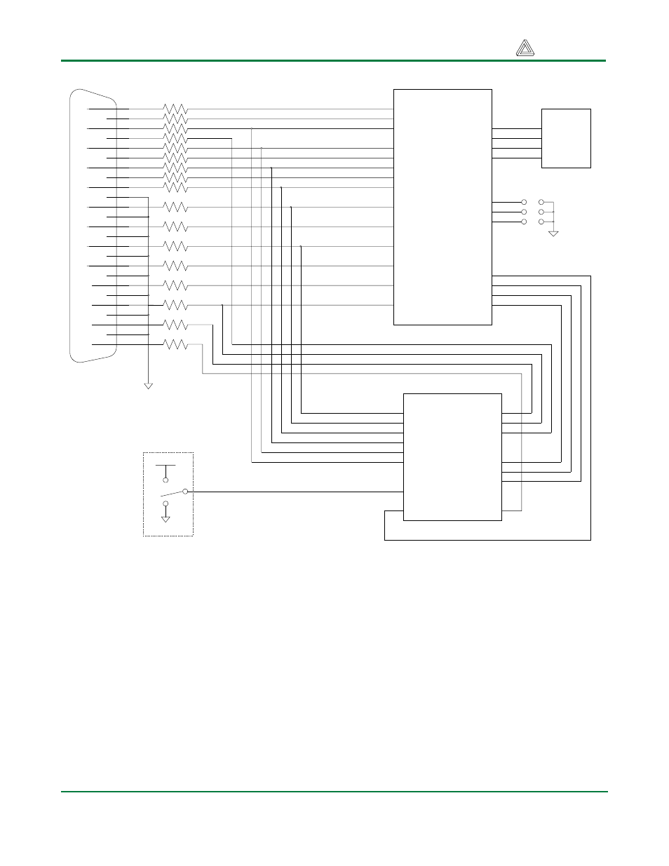
Figure 2. Parallel port and programming circuit schematic
Serial Port
The D2 serial port uses a Maxim MAX3386E RS-232 voltage converter to generate the required RS-
232 voltages. Five signals are connected through the RS-232 converter, allowing for partial hardware
handshaking. The serial port pin definitions and circuit are shown in Figure 3. The serial port is
provided, in part, to support the Xilinx MicroBlaze embedded RSIC processor core available from the
Xilinx website.
The two devices connected to either end of a serial cable are designated as the Data Terminal
Equipment (DTE) and the Data Communications Equipment (DCE). The DCE was originally
conceived to be a modem, but now many devices connect to a computer as a DCE. A DTE device uses
a male DB-9 connector, and a DCE device uses a female DB-9 connector. The DTE is considered the