On-board i2c peripheral device, Pmod connectors, User i/o devices – Digilent 32MX7 User Manual
Page 8: Jumper settings for i, C pull-up resistors, The cerebot 32mx7 provides one on-board i
Cerebot 32MX7 Reference Manual
www.digilentinc.com
page 8 of 19
Copyright Digilent, Inc. All rights reserved. Other product and company names mentioned may be trademarks of their respective owners.
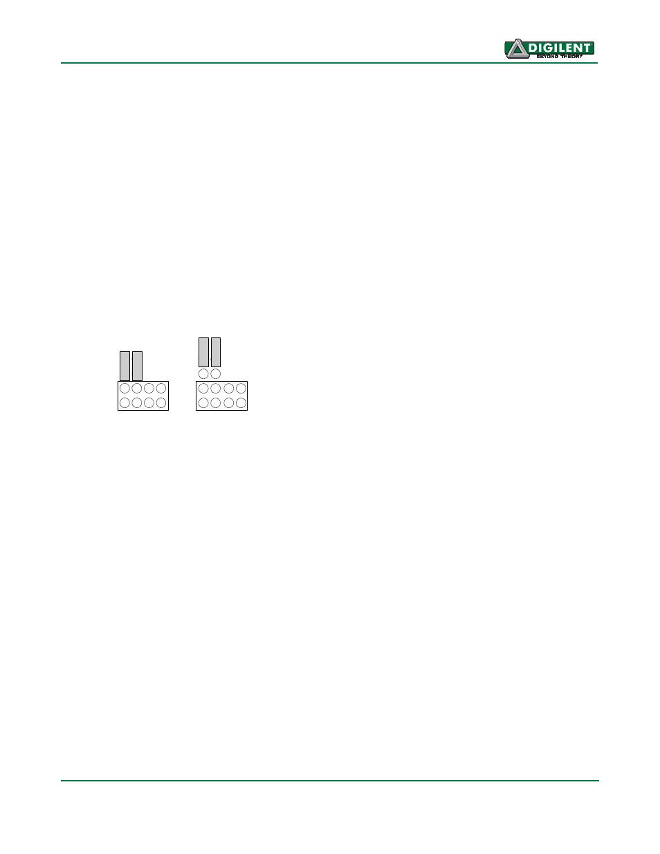
disabled via jumper blocks on the ‘pull-up’
positions on connector J2. The pull-ups are
enabled by installing shorting blocks and are
disabled by removing the shorting blocks. The
shorting blocks are placed so that they line up
with the SCL and SDA labels on the board.
Only one device on the bus should have the
pull-ups enabled.
The pull-up resistors on I2C #2 on the Cerebot
32MX7 board are actually implemented using
current mirrors rather than simple resistors.
These current mirrors source approximately
1.7mA. The use of current mirrors provides
faster rise times on the I2C signals and
provides the ability to drive longer cable runs
reliably than would be the case with simple
pull-up resistors.
S
C
L
S
D
A
S
C
L
S
D
A
Pull-ups
Enabled
Pull-ups
Disabled
3
V
3
G
N
D
3
V
3
G
N
D
Jumper Settings for I
2
C Pull-Up Resistors
On-Board I2C Peripheral Device
The Cerebot 32MX7 provides one on-board I
2
C
peripheral device, a Microchip 24LC256 serial
EEPROM. This device is connected to I2C #1.
The 24LC256 is a 256Kbit (32Kbyte) serial
EEPROM device to provide non-volatile
memory storage. The device address for the
24LC256 is 1010000 (0x50).
Refer to the Microchip data sheet for detailed
information on the operation of this device.
Pmod Connectors
The Cerebot 32MX7 has six Pmod connectors
for connecting Digilent Pmod peripheral
modules. Digilent Pmods are a line of small
peripheral modules that provide various kind of
I/O interfaces. The Pmod line includes such
things as button, switch and LED modules,
connector modules, LCD displays, high current
output drivers, and many others.
There are two styles of Pmod connector: six-
pin and twelve-pin. Both connectors use
standard pin headers with 100mil spaced pins.
The six-pin connectors have the pins in a 1x6
configuration, while the twelve-pin connectors
use a 2x6 configuration. The six-pin
connectors provide four I/O signals, ground
and a switchable power connection. The
twelve-pin connectors provide eight I/O
signals, two power and two ground pins. The
twelve-pin connectors have the signals
arranged so that one twelve-pin connector is
equivalent to two of the six-pin connectors.
The power connection is switchable between
the regulated 3.3V main board supply and the
unregulated input supply.
Digilent Pmod peripheral modules can either
be plugged directly into the connectors on the
Cerebot 32MX7 or attached via cables.
Digilent has a variety of Pmod interconnect
cables available.
See the “Connector and Jumper Block Pinout
Tables” section below for more information
about connecting peripheral modules and other
devices to the Cerebot 32MX7.
These tables
indicate the mapping between pins on the
PIC32MX795 microcontroller and the pins on
the various connectors.
User I/O Devices
The Cerebot 32MX7 board provides three push
button switches for user input and four LEDs
for output. The buttons, BTN1 and BTN2 are
connected to I/O pins RG6, RG7 and RD13
respectively. To read the buttons, bits 6 and 7
of PORTG and/or bit 13 of PORTD must be set
as inputs by setting the corresponding bits in
the TRISG and/or TRISD register and then
reading the PORTG and/or PORTD register.
When a button is pressed, the corresponding
bit will be high (‘1’).