Jumper blocks – Digilent Cerebot II Board User Manual
Page 10
Cerebot II Reference Manual
Digilent, Inc.
www.digilentinc.com
page 10 of 10
Copyright Digilent, Inc. All rights reserved. Other product and company names mentioned may be trademarks of their respective owners.
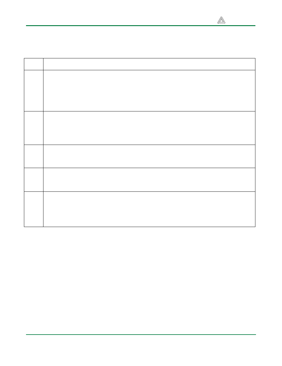
Jumper Blocks
Jumper
Label
Function
JP1
Voltage regulator bypass
This jumper is used to select the voltage source to power the main board-regulated power
bus, VCC. Place the shorting block in the ‘normal’ position to power the board from the on-
board 3.3V regulator. Place the shorting block in the ‘bypass’ position to power the board
from an externally regulated supply. This connects the unregulated power bus, VU, to the
main regulated power bus, VCC.
JP2
Servo power bus
Connect the RC hobby servo power bus to the unregulated supply bus, VU. When a
shorting block is in place on this jumper, servo power is supplied from VU on the Cerebot II.
If the jumper block is removed, the RC hobby servo power bus must be supplied with a
source connected to the screw terminal block, J10.
JP3
VU voltage sense circuit enable
When JP3 is installed, the VU voltage monitor circuit is connected to ADC0. See page 3 of
this reference manual for a description of the voltage monitor circuit.
JP4
VS voltage sense circuit enable
When JP4 is installed, the VU voltage monitor circuit is connected to ADC1. See page 3 of
this reference manual for a description of the voltage monitor circuit.
JPA -
JPH
Pmod headers
Any of the eight Pmod headers can be connected to use either regulated or unregulated
power. To use regulated power, place the jumper block over the center pin and the pin
marked VCC. To use unregulated power, place the jumper block over the center pin and the
pin marked VU.