Digilent Cerebot II Board User Manual
Digilent Hardware
C
C
e
e
r
r
e
e
b
b
o
o
t
t
I
I
I
I
™
™
B
B
o
o
a
a
r
r
d
d
R
R
e
e
f
f
e
e
r
r
e
e
n
n
c
c
e
e
M
M
a
a
n
n
u
u
a
a
l
l
®
w w w. d i g i l en t in c . c om
Revision: February 9, 2009
Note: This document applies to REV B of the board.
215 E Main Suite D | Pullman, WA 99163
(509) 334 6306 Voice and Fax
Doc: 502-128
page 1 of 10
Copyright Digilent, Inc. All rights reserved. Other product and company names mentioned may be trademarks of their respective owners.
Overview
The Cerebot II board is a useful tool for
embedded control and robotics projects for
both students and hobbyists.
Its versatile design and programmable
microcontroller lets you access numerous
peripheral devices and program the board for
multiple uses. The board has many I/O
connectors and power supply options and
supports a number of programming options
including the free Atmel AVR
®
Studio 4, and
WinAVR.
The Cerebot II has a number of connections
for peripheral devices. It provides eight
connectors for attaching Digilent Pmod™
peripheral modules. Digilent peripheral
modules include H-bridges, analog-to-digital
and digital-to-analog converters, speaker
amplifier, switches, buttons, LEDs, as well as
converters for easy connection to RS232,
screw terminals, BNC jacks, servo motors, and
more.
Features include:
•
an ATmega64L microcontroller
•
eight hobby RC servo connectors
•
eight Pmod connectors for Digilent
peripheral module boards
•
an on-board voltage regulator
•
multiple flexible power supply jumper
options
•
support for the Digilent JTAG-3 Parallel
and JTAG-USB programming cables
•
support for the Atmel AVRISP in-
system programmer
•
support for the Atmel AVR JTAGICE
mkII debugging tool
•
ESD protection and short circuit
protection for all I/O pins.
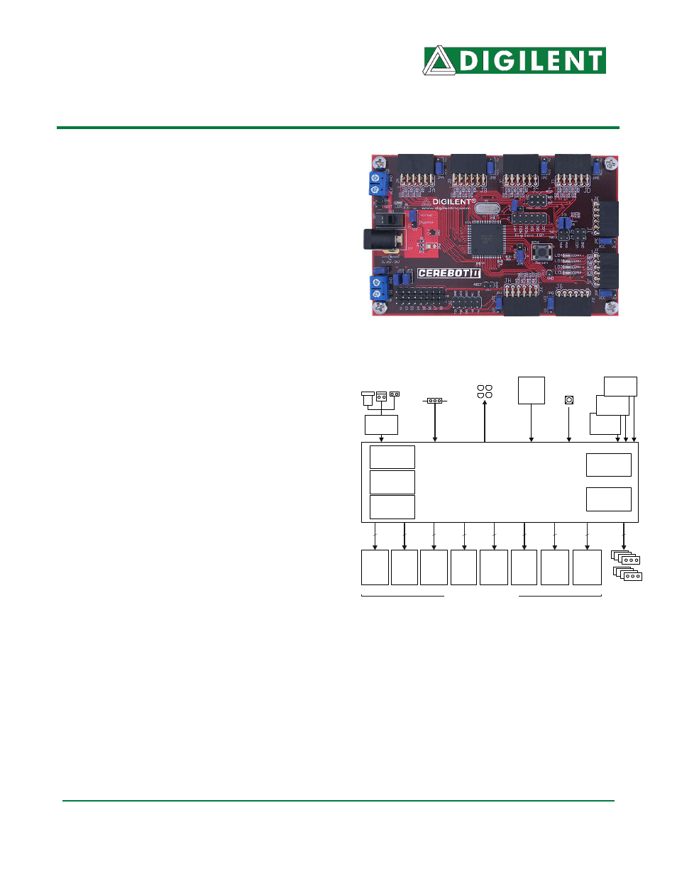
Cerebot II Circuit Diagram
Atmel
ICE port
Atmel
ISP port
JA
Mem
Adr/
Data
ATmega64L
TQ64
Eight Pmod connectors
8MHz
crystal
64K Flash
(Internal)
Reset
button
4 LEDs
Digilent
ISP port
8
2K EEPROM
(Internal)
Internal
Oscillator
UART, SPI,
&TWI ports
3.3V
regulator
JB
Mem
Adr
JC
Mem
Ctl
UART
JD
SPI
TWI
UART
JE
H-bridge
JF
H-bridge
&
LEDs
JG
H-bridge
Various power
connectors
8
8
8
4
4
4
8
Eight servo
connectors
JH
Analog
&
JTAG
8
4K SRAM
(Internal)
User Input
Jumper
GND
VCC