Vhdci connector – Digilent 210-179P User Manual
Page 6
VmodCAM Reference Manual
www.digilentinc.com
page 6 of 6
Copyright Digilent, Inc. All rights reserved. Other product and company names mentioned may be trademarks of their respective owners.
Image Configuration Example
The following commands can be inserted into
the initialization sequence to configure the
camera for 16-bit RGB565 output and
1600x1200 resolution in video capture mode.
Note that most of these parameters are driver
variables and can be accessed as described in
the
Control Interface section above.
1. V[0x2797] = 0x0030; Context B output
format RGB565
2. V[0x2707] = 0x0640; Output width 1600
3. V[0x2709] = 0x04B0; Output height
1200
4. V[0x275F] = 0x0000; Crop X0 0
5. V[0x2763] = 0x0000; Crop Y0 0
6. V[0x2761] = 0x0640; Crop X1 1600
7. V[0x2765] = 0x04B0; Crop X1 1200
8. V[0x2741] = 0x0169; Auto
exposure/gain fix
9. V[0xA120] = 0x00F2; Auto White
Balance, Auto Exposure, Auto
Histogram, Video On in Capture mode
10. V[0xA103] = 0x0002; Sequencer
Refresh Mode
11. Read V[0xA103] until == 0x0000,
meaning the command got executed.
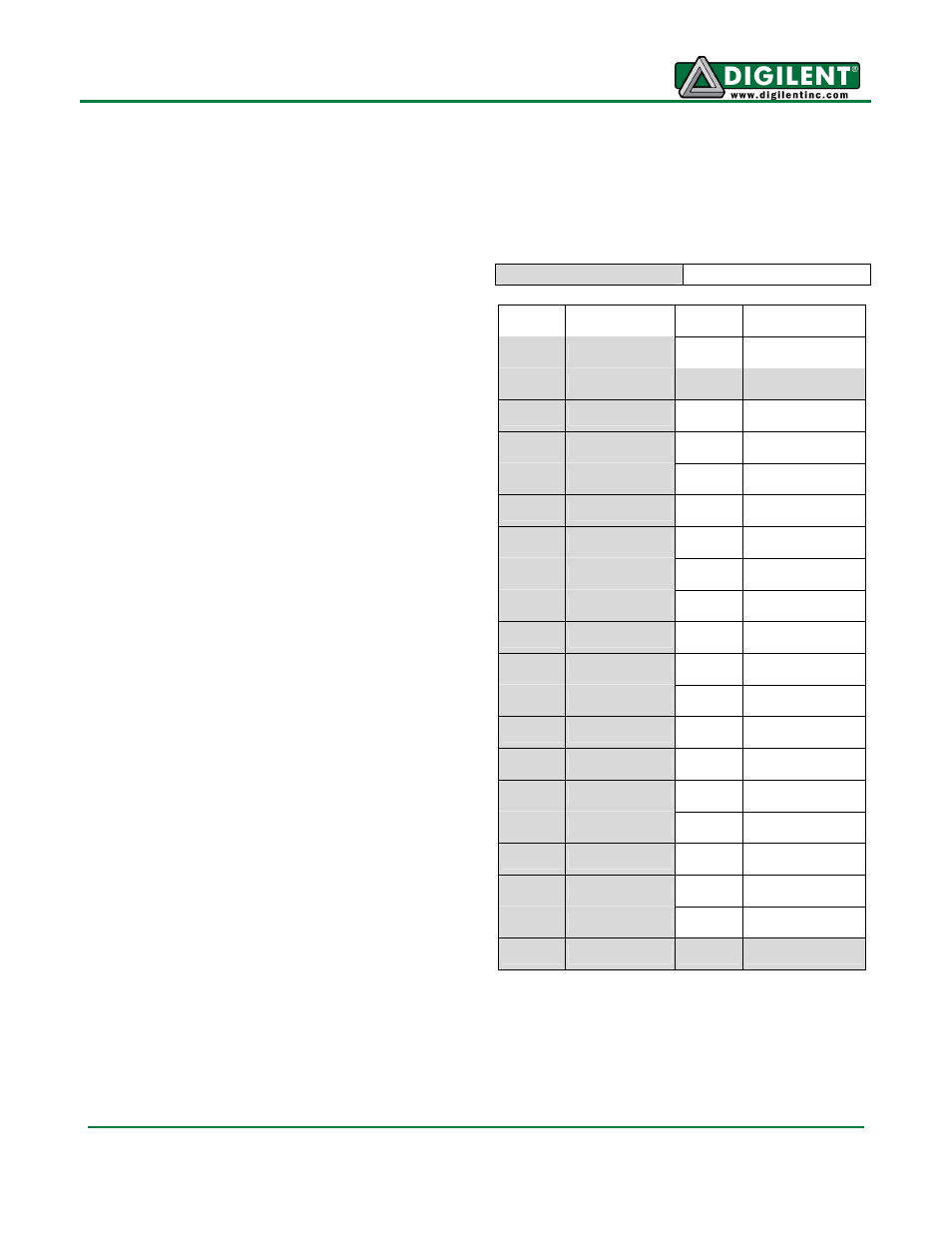
VHDCI Connector
The VmodCAM should only be attached to the
system board once the signals driven by the
system board are defined.
CAM1 refers to IC2, the camera on the lower
part of the PCB.
CAM2 refers to IC6, the camera on the upper
part of the PCB.
VHDCI CAM
VHDCI CAM
IO1-P CAM1_D3
IO1-N VDD-EN
IO2-P CAM1_D4
IO2-N CAM1_D2
IO3-P CAM1_D5
IO3-N CAM1_RESET
IO4-P CAM1_D6
IO4-N CAM1_MCLK
IO5-P CAM1_D7
IO5-N CAM1_PWDN
IO6-P CAM1_FV
IO6-N CAM1_SCL
IO7-P CAM1_LV
IO7-N CAM1_SDA
IO8-P CAM1_D0
IO8-N NC
IO9-P CAM1_D1
IO9-N NC
IO10-P CAM1_PCLK IO10-N NC
IO11-P CAM2_PCLK IO11-N NC
IO12-P CAM2_D2
IO12-N CAM2_PWDN
IO13-P CAM2_D3
IO13-N CAM2_RESET
IO14-P CAM2_D4
IO14-N CAM2_MCLK
IO15-P CAM2_D5
IO15-N NC
IO16-P CAM2_D6
IO16-N CAM2_SCL
IO17-P CAM2_D7
IO17-N CAM2_SDA
IO18-P CAM2_FV
IO18-N NC
IO19-P CAM2_LV
IO19-N NC
IO20-P CAM2_D0
IO20-N CAM2_D1
Table 3 VHDCI Connector Pin-Out
Camera Output
Camera Input