Digilent 210-179P User Manual
Page 4
VmodCAM Reference Manual
www.digilentinc.com
page 4 of 6
Copyright Digilent, Inc. All rights reserved. Other product and company names mentioned may be trademarks of their respective owners.
Enable output:
1. R[0x301A] = 0x02CC; parallel enable,
drive pins, start streaming.
Image Processing
Raw sensor data coming from the pixel array is
fed to a color processing pipeline called an
image flow processor (IFP). This is where all
the image processing, correction, scaling,
interpolation, and output formatting algorithms
are applied.
The IFP can also be bypassed, causing the
camera to output the uncompressed raw 10-bit
Bayer data in this mode.
The IFP is controlled indirectly, through
microprocessor variables and the sequencer.
The IFP can be controlled directly by
accessing its hardware registers, but normally
the on-chip microprocessor regularly adjusts
these parameters.
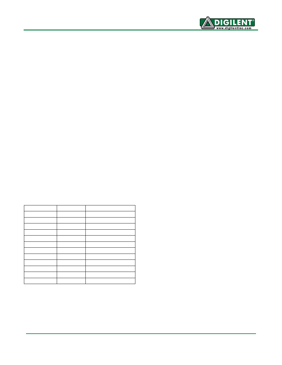
Output Formats
Mode
Byte
D7:D0
RGB565
Odd
R
7
R
6
R
5
R
4
R
3
G
7
G
6
G
5
Even
G
4
G
3
G
2
B
7
B
6
B
5
B
4
B
3
RGB555
Odd
0R
7
R
6
R
5
R
4
R
3
G
7
G
6
Even
G
5
G
4
G
3
B
7
B
6
B
5
B
4
B
3
RGB444x
Odd
R
7
R
6
R
5
R
4
G
7
G
6
G
5
G
4
Even
B
7
B
6
B
5
B
4
0000
RGBx444
Odd
0000R
7
R
6
R
5
R
4
Even
G
7
G
6
G
5
G
4
B
7
B
6
B
5
B
4
YUV
4*i
Cb
4*i+1
Y
4*i+2
Cr
4*i+3
Y
Contexts
The microprocessor uses two contexts, each
with their own set of parameters. Context A is
preconfigured for preview mode. Context B is
for snapshot and video capture.
You can set the parameters using the two-wire
interface to command the sequencer to switch
contexts. If the parameters being modified
belong to the active mode, the changes only
take effect after the Refresh and Refresh Mode
commands are executed.
Sequencer
The sequencer is a state machine responsible
for coordinating events triggered by the user.
You can query the current state and instruct
the sequencer to change state.
The sequencer command variable V[0xA103]
accepts the following values:
•
0-Run
•
1-Go to Preview
•
2-Go to Capture
•
3-Go to Standby
•
4-Do lock
•
5-Refresh
•
6-Refresh mode
For the video capture, the Video bit (bit 1)
needs to set in variable V[0xA120]. Otherwise,
the capture state will only take a single
snapshot.
The sequencer state variable V[0xA104] reads:
•
0-Initialize
•
1-Mode Change to Preview
•
2-Enter Preview
•
3-Preview
•
4-Leave Preview
•
5-Mode Change to Capture
•
6-Enter Capture
•
7-Capture
•
8-Leave Capture
•
9-Standby