Digilent AVR Programmer User Manual
Page 6
Digilent AVR Programmer Reference Manual
Digilent, Inc.
www.digilentinc.com
page 6 of 8
Copyright Digilent, Inc. All rights reserved. Other product and company names mentioned may be trademarks of their respective owners.
tune the RC oscillator to operate more closely
at its nominal frequency. The calibration values
are stored in a special non-volatile memory
that is not accessible at run time in all devices.
If the oscillator calibration feature is used, it is
typical for the calibration value to be read from
the device and stored in a known location in
memory while programming the device. The
calibration value will then be read from the
known memory location and written to the
calibration register during the startup
initialization of the firmware program running
on the device.
The Internal Oscillator Calibration user
interface provides facilities for reading a
calibration value from the device and writing it
to a specified location in either the program
flash memory or the data EEPROM memory.
The Calibration Frequency drop-down list
box contains the list of calibration values
available for the device.
The Read button reads the selected calibration
value and displays it in the Value field.
The Value field displays the calibration value
read from the device or the value to be written
to the device. If entered manually, it is entered
as a single hexadecimal byte value.
The Address field specifies the memory
address at which the calibration value will be
written. The Program Flash and Data
EEPROM radio buttons select the memory to
which this address refers.
The Write button writes the byte displayed in
the Value field to the specified memory
address.
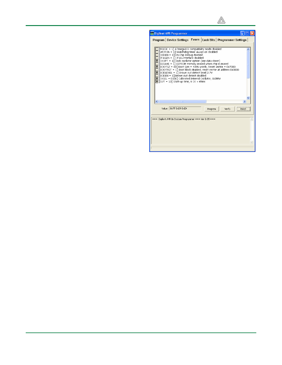
Fuses Tab
The Fuses tab is used to read and set the fuse
bits in the device. This tab includes a fuses list,
a Value field, and some control buttons.
The fuses list displays the available sets of
fuse bits as described by the selected part
description file. The contents of the fuses list
varies depending on the device selected in the
AVR Device field of the Program tab. Refer to
the device’s Atmel data sheet for a description
of its fuse bits. If Manual Settings is chosen for
the AVR Device, then this list will be empty.
The Value field shows the binary value for the
fuse bytes that corresponds to the current
selections made in the fuses list. The number
of bytes shown corresponds to the number of
fuse bytes defined for the selected AVR
device.
If a part description file is selected in the AVR
Device field of the Program tab, this field is
inactive and merely reports the binary value
corresponding to the selections in the fuses
list. If Manual Settings is chosen in the AVR
Device field of the Program tab, this field is
active and the fuses list will be empty. In this
case, enter the desired value for the fuses as
one to three hexadecimal values (depending
on the number of fuse bytes in the device).
Note that for most fuse bits, setting the bit to 0
enables the function. The values are entered