Digilent AVR Programmer User Manual
Page 5
Digilent AVR Programmer Reference Manual
Digilent, Inc.
www.digilentinc.com
page 5 of 8
Copyright Digilent, Inc. All rights reserved. Other product and company names mentioned may be trademarks of their respective owners.
can then be used to program another device.
The read operation may not work correctly if
the settings of the lock bits prevent reading
back part of the device memory.
Data EEPROM Section
The Data EEPROM section contains the same
user interface elements with the same
functionality as the Program Flash section.
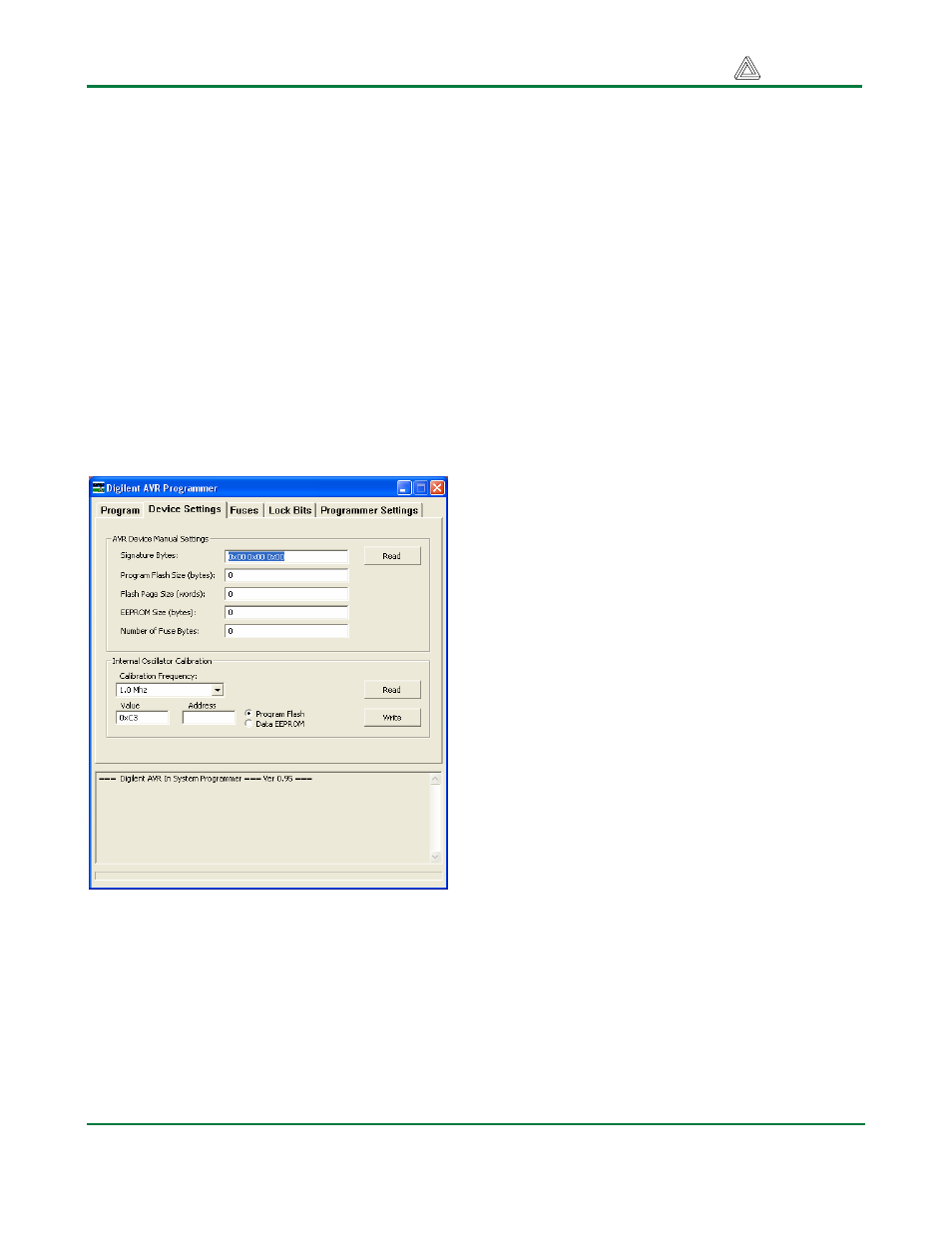
Device Settings Tab
The Device Settings tab is used to examine or
set the device properties used to control the
device programming process. The tab also
contains the controls used to manage the
Internal Oscillator Calibration feature.
AVR Device Manual Settings Section
This section includes several fields containing
the device properties that control the device
programming process. If Manual Settings is
chosen in the AVR Device list box on the
Program tab, then these fields will be active
and you must enter the appropriate values into
these fields. If a part description file is chosen
instead of Manual Settings, then these fields
will be inactive and will display the information
read from the part description file.
For entering the settings manually, the
information needed for these fields can be
found in the “Memory Programming” section of
the data sheet for the specific AVR device.
The Signature Bytes field contains the three-
byte signature for the device. If entered
manually, it is entered as three hexadecimal
values separated by spaces. For example, the
signature for an ATmega64 is entered as 0x1E
0x96 0x02 .
The Read button causes the signature to be
read from the device and displayed in the
Signature Bytes field.
The Program Flash Size (bytes) field
specifies the size of the program flash
memory. It is entered as a decimal integer
number.
The Flash Page Size (words) field specifies
the size of the program flash page buffer.
Some AVR devices use a page buffer to hold
pages of program data during the
programming process. This is entered as a
decimal integer number giving the size of the
page buffer in 16-bit words. For AVR devices
that are not paged, the decimal value 1 should
be placed in this field.
The EEPROM Size (bytes) field specifies the
size of the data EEPROM memory. It is
entered as a decimal integer number.
The Number of Fuse Bytes field specifies the
number of fuse bytes in the device. AVR
devices have between one and three fuse
bytes, depending on the specific device.
Internal Oscillator Calibration Section
Most AVR devices have an internal RC
oscillator available as one of the clock sources.
This oscillator can be calibrated using
calibration values written into each device at
the factory. A calibration value is a byte value
that can be written to the calibration register to