Digilent Embedded Linux User Manual
Page 7
Using Zynq with Linux
www.digilentinc.com
page 7 of 23
Copyright Digilent, Inc. All rights reserved. Other product and company names mentioned may be trademarks of their respective owners.
In Example 4, two devices are declared: the GPIO controller for Processing System of ZYNQ,
gpiops, and the on-board OLED display, zed_oled.
The device tree names the node for the GPIO controller gpiops, with the generic name of gpio and
a base address starting from 0xe000a000, according to conventional naming of the node. The full
name of gpiops is gpio@e000a000, as shown in the /sys file system and /proc file system. The
compatibility string of the GPIO controller is xlnx,ps7-gpio-1.00.a. The device will use the
xlnx-gpiops driver by matching the compatibility string of the node with that defined in the driver
source code. The reg property defines the gpiops GPIO controller by a physical address that begins
from 0xe000a000 with a size of 0x1000 (64KB). The interrupt is connected to the global interrupt
controller gic, as the phandler of gic (&gic in the DTS) passes to the interrupt-parent
property.
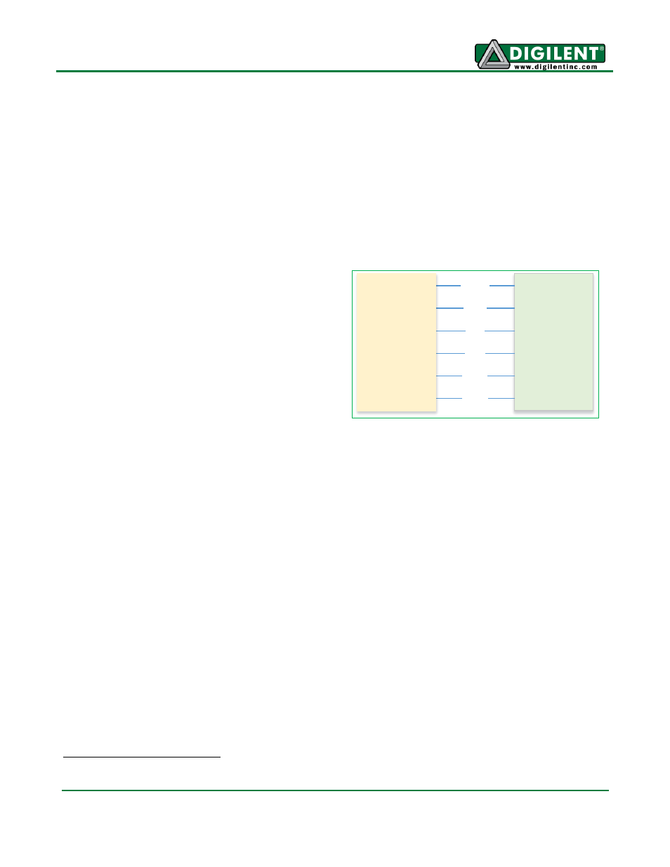
The second node shown in Example 4 is a device
with full name zed_oled. It is for the on-board
OLED device on the ZedBoard. In the hardware
design, the OLED is connected directly to the
gpiops GPIO controller (pin 55 to pin 60), as
shown in Figure 2. So, you can implement the driver
of the on-board OLED for the ZedBoard by getting
the GPIO pin number from the zed_oled device
node and toggling the corresponding GPIO pins
according to the OLED display transmission
protocol. As a result, the device zed_oled is not
actually a device controller with a physical register
space mapped in memory space, but a virtual device defined so that the driver in the kernel knows
which GPIO pins are used. So, there is no base address, no register space, no @
part in the full name of the device nodes, and no reg properties in the device tree. The device does
have a compatibility string so that the corresponding pmodoled-gpio driver can be registered for the
device and toggle the GPIO pins to control the OLED display. There are also several properties that
specify which GPIO pins to use.
1
Device Tree Compilation
The DTS file needs to be compiled into a DTB file that the kernel can understand. The device tree
compiler (DTC), located under scripts/dtc in the Linux kernel source, will compile the DTS file into
a DTB file with the command:
$ ./scripts/dtc/dtc -I dts -O dtb -o devicetree.dtb digilent_zed.dts
The DTC compiler can also de-compile a DTB file back to the DTS file with the command:
$ ./scripts/dtc/dtc -I dtb -O dts -o digilent_zed.dts devicetree.dtb
You can view other options for the DTC compiler with the -h option:
1
Structure gpio-specifier is passed to the properties (e.g. vbat-gpio = <&gpiops 55 0>). Refer to
Documentation/devicetree/bindings/gpio/gpio.txt for more details.
OLED
VBAT
VDD
RES
D/C
SCLK
SDIN
GPIO
55
56
57
58
59
60
Figure 2. OLED Hardware Connection