Toshiba FS-160 SERIES User Manual
Page 43
Attention! The text in this document has been recognized automatically. To view the original document, you can use the "Original mode".
6. DISPLAY
An HMCS-45A is used for the display controller indentified by ICS.
Receiving the 4 bit parallel display data sent through connector
CN3, it displays the same contents (10 digits) on the FIU and BIU
and controls the buzzer.
After being input to the display controller, the display data from
the CPU is output from each port as the segment plate signals and
the grid signal for each digit. These signals are amplified by ICl
to ICG and then sent to the FIU and BIU in parallel. The buzzer
control signal is output from the D1 port and is driven by IC7 and
transistor Ql.
There are six types of power supplies to be delivered to the
display:
-5V, +5V, -VD, VFl, VF2, VM. They are sent from the
power supply unit through connector CN3. +5V and -5V are used as
power supplies for the ICs, -VD, VFl, and VF2 as power supplies for
the fluorescent display tube, and VM for driving the buzzer.
Table 6.1 lists the port functions of the printer controller.
Common to FIU and BIU
ICS
lOG
V
p
1 1
n
1 1
1
J
r
/
L
1 L
—
y
V
V
2G
IG
S(a)
S(g)
(
1
/
2
)
t)
(DP)
R20
R2*3
D1
D0
R30
INT0
R33
R40
R41
ROO
ROl
R02
D2
D3
/
/
i
\
KU J
1
ILMCS -45A
ACKito CPU)
CS
PA0
PAl
PA2
PA3
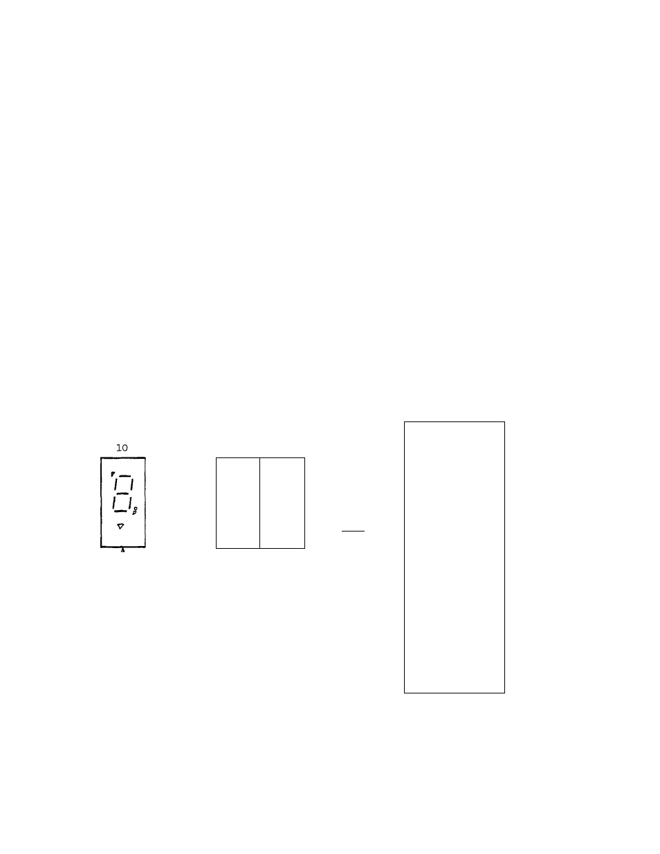
Fig. 6.1 Display Circuit Block Diagram
-26-