Sideburner – Kenmore 415.161108 User Manual
Page 20
Attention! The text in this document has been recognized automatically. To view the original document, you can use the "Original mode".
13
Sideburner
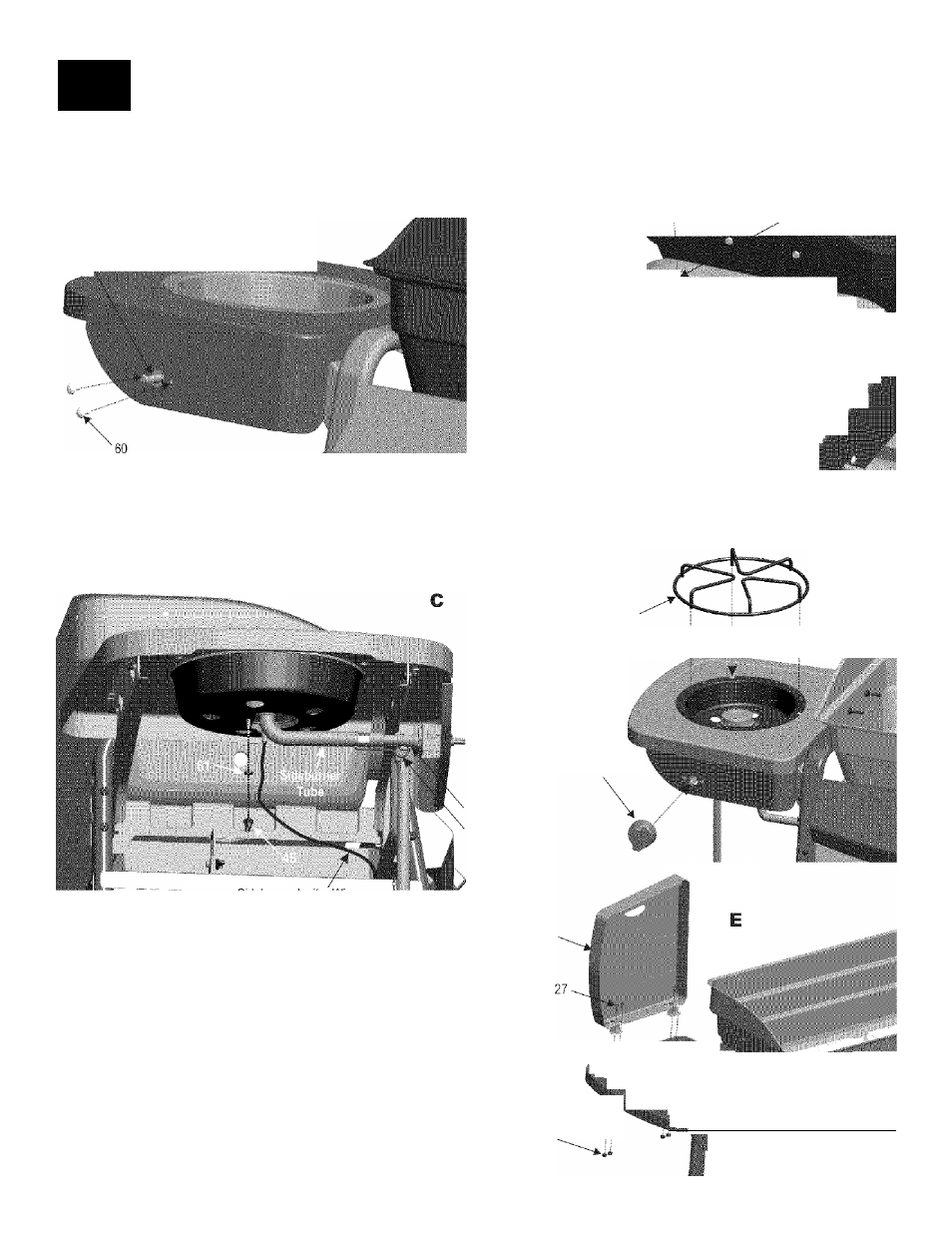
: Attach sideburner valve with #8-32x3/8" machine screws (A).
Attach sideburner pan with #8x3/8" self-tap screws and 5mm ID 9mm OD fiber washers. Place sideburner into shelf (B).
Make sure valve is inside sideburner tube. Attach sideburner with wing nut and 5mm ID 9mm OD fiber washer. Insert one end
of burner clip into hole in sideburner tube and hook other end around valve manifold. Attach sideburner ignitor wire (C).
Press sideburner control knob onto valve stem and sideburner grate onto shelf (D).
: Attach hinges to back of shelf with #10-24x1/2" screws and #10-24 nuts (Ej.
47------- »4
__ 61
Siuoburr or Va vo
Sideburner
\
4f T
bw
^
wmbbwwbbww
Correctly assembled burner-to-valve engagement
Sideburner Grate
Control Knol
Sideburner Valve
SideBurner Clip
Sideburner Ignitor Wire
60
#8-32x3/8"
Screws
Qty
. 2
T
Cl
f
Sideburner Lid
47
#8x3/8”
Self-Tap Screws
Qty.3
45
Sideburner Clip
Qty:1
46
Wing Nut
Qty. 1
27
13
61
5mm ID, 9mm OD
^ 3
#10-24X1/2" Screw #10-24 Flange Nut Fiber Washers
Qty. 4
Qty. 4
Qty. 4
^_____________________
20*464810408