Control panel and upper firebox supports – Kenmore 415.161108 User Manual
Page 16
Attention! The text in this document has been recognized automatically. To view the original document, you can use the "Original mode".
Control Panel and Upper Firebox Supports
Stand cart upright.
In front, fit control panel between left and right legs. Insert #10-24x2" screws to hold panel in place. Place upper firebox
supports onto screws making sure angle side is facing the front and attach with #10-24 flange nuts.
: In back, attach upper firebox support with #10-24x2" screws and #10-24 flange nuts.
Control Parol
17
...
n
M.......
I ..........
17
#10-24x2" Screw
Qty
. 8
«
■
13
#10-24 Flange Nut
Qty
. 8
E
13
g
'Upper Firebox
Support
iii^M
M
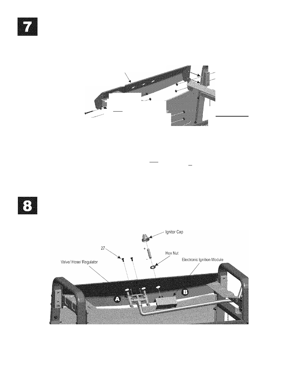
Valve/Hose/Regulator and Electronic Ignition Module
Attach valve/hose/regulator assembly to control panel with #10-24x1/2" screws (A).
Remove ignitor cap and plastic hex nut from Electronic Ignition module assembly. Insert module into the opening on control panel
and attach with the removed hex nut. Place AA battery into module slot with positive end (+) facing outward. Screw ignitor cap onto
module (B).
27
#10-24X1/2" Screw
Qty.2
15*464810408