Carl Goldberg GBGA1085 User Manual
Page 9
9
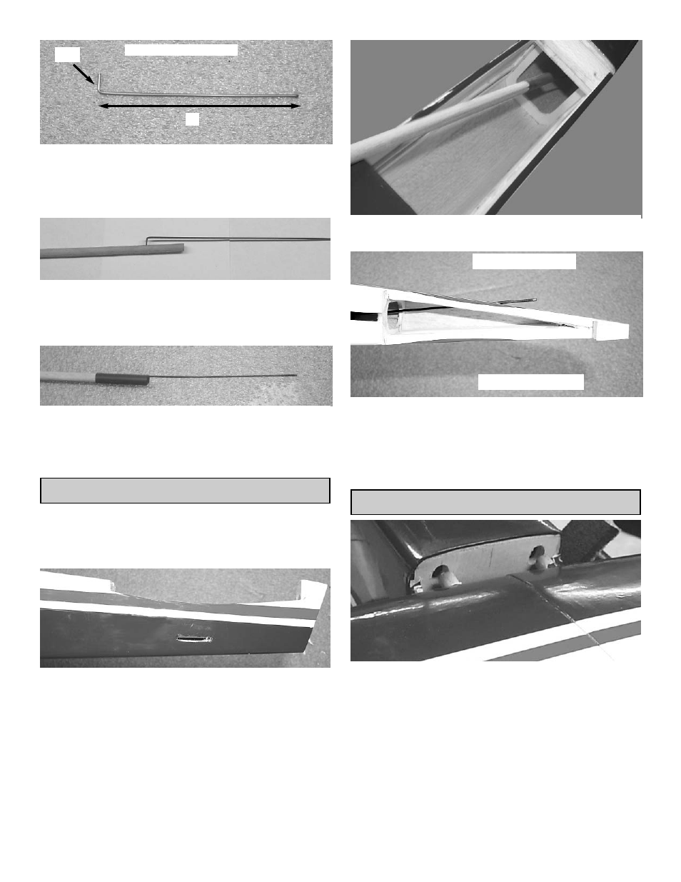
1/2”
6”
NON THREADED WIRE
5.
Starting at the unthreaded end of the 1.5mm x
25cm wire, bend the last 3/8” up at a 90
degree angle.
Measure the length of the wire 6” from the
bend and cut the wire.
6.
Insert the wire into the hole in the wood
pushrod and push down into the groove.
Glue the wire to the wood pushrod using
medium CA glue.
8.
Slide the heat shrink tubing over the pushrod
and shrink using a blow drier.
Glue the tubing to the wood pushrod using
thin CA glue.
This finishes the rudder pushrod.
INSTALLING PUSHRODS
1.
Collect the following parts
(1) Elevator Pushrod
(1) Rudder Pushrod
(1) Fuselage
2.
Find the hole under the stabilizer on both
sides of the fuselage.
Cut the covering over each of the push rod
exit holes.
3.
Insert the rudder pushrod into the fuselage
through the wing saddle area.
4.
Insert the wire into the hole in the right side of
the fuselage.
Repeat these steps for the elevator pushrod
making it exit the left side of the fuselage.
Tape the pushrods to the side of the fuselage
inside the wing saddle area.
WING INSTALLATION ON FUSELAGE
1.
Insert the wing into the wing saddle of the
fuselage by sliding the dowels on the front of
the wing into the holes in the former just for-
ward of the wing saddle.
Insert two 3.5mm socket head screws and the
3.5mm washers through the bolt plate and the
wing and then begin to screw into the blind
nut in the fuselage. Screw down until the
screws are touching the wing tight.
Rudder Pushrod
Elevator Pushrod