Carl Goldberg GBGA1085 User Manual
Page 6
6
3.
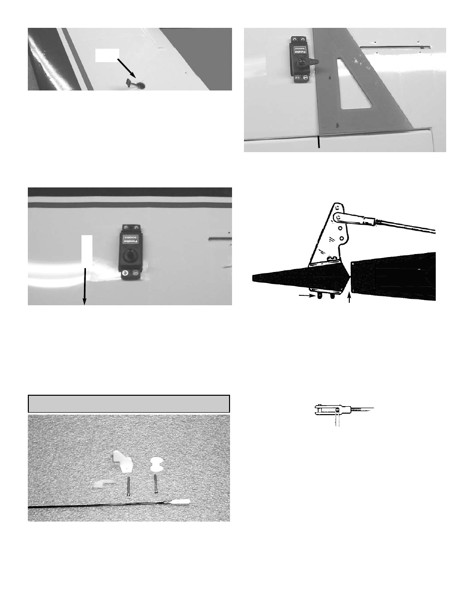
Gently pull the string out of the aileron servo
hole and tie it or tape it to the servo wire.
From the top of the wing remove the covering
over the hole that is next to the center rib.
Pull the servo wire towards the center of the
wing using the string inside the wing.
When the servo plug exits the wing then tape
the plug to the top of the wing.
4.
Slide the servo into the servo hole in the wing
with the out put arm towards the aileron.
Using the screws that come with your radio,
mount the servo into the wing.
Repeat these steps for the other half of the
wing, so that both servo extensions are exiting
the holes in the center of the wing and the ser-
vos are installed in the wing.
Aileron
Tape
AILERON CONTROL HORN INSTALLATION
1.
Collect the following items
(2) Large control horn with back plate
(4) 3/4" screw
(2) Metal metal clevis
(2) 10” threaded rod
(2) Swivel keepers
2.
With the aileron servo arm in place, make a
mark at a 90º degree angle to the trailing edge
and in line with the servo arm.
1.5mm x 20mm
MACHINE SCREWS
METAL CLEVIS
CONTROL
HORN
PLACE CONTROL HORN AT HINGE LINE
Bottom of wing
Wing is upside
down in this view
3
.
Position the control horn so that the clevis
holes are right next to the hinge line, as
shown.
4.
Using a 3/32" drill bit, make a hole in each
screw location.
Mount the control horn with the 1.5mm x
20mm machine screws.
5.
Thread the 10" rod onto the metal clevis.
Make sure the rod shows in the center of the
metal clevis.
Place the metal clevis in the second hole from
the top on the control horn.