Carl Goldberg GBGA1085 User Manual
Page 7
7
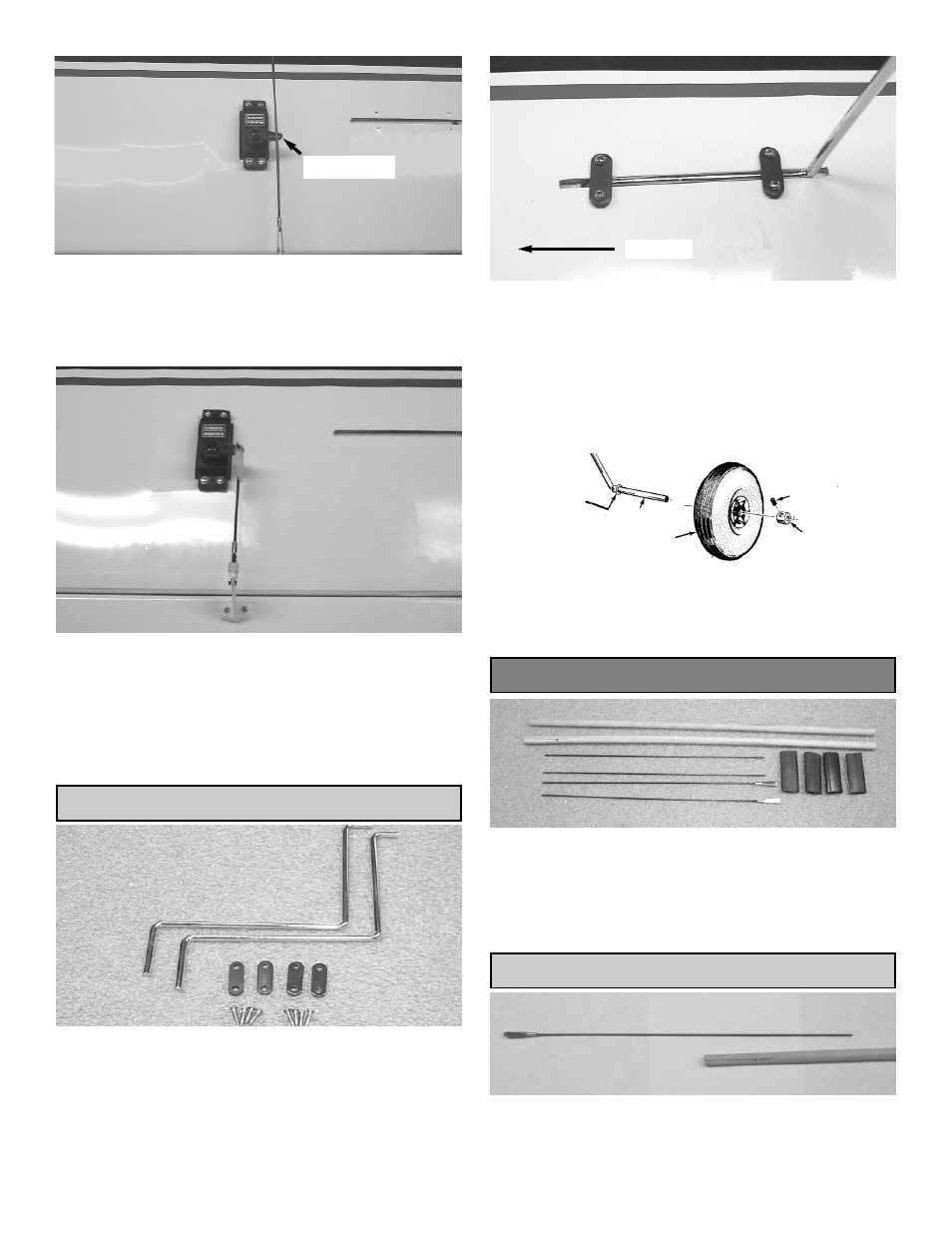
6.
Make sure the aileron is in neutral (level) posi-
tion, mark where the wire meets the hole on
the servo arm.
Remove the wire and cut it about 1/2" beyond
the mark.
Mark wire
7.
Bend the wire 90 degrees up at the mark you
just made.
Slide the swivel keeper over the wire and clip
onto the pushrod.
Slide the silicone keeper over the clevis.
Repeat these steps for the other aileron servo.
MAIN GEAR & WHEEL INSTALLATION
1.
Collect the following items:
(2) Landing gear wire
(8) 2 x 5/16"screw
(4) Landing gear strap
(3) 2-1/2" wheel
(4) Wheel collar
(4) Allen head set screw
2.
Locate the landing gear slots in the bottom of
the wing and remove the covering material.
Insert the shorter end of the gear into the hole
in the bottom of the slot, so that it points
toward the center of the wing.
3.
Use two Metal straps and four screws on each
side to secure the wire gear.
4.
Install the wheels on the axles, as shown.
First the wheel collar goes on, followed by the
wheel, then the second wheel collar, and the
set screw. Tighten the set screw.
AXLE
WHEEL
SET SCREW
WHEEL COLLAR
WHEEL COLLAR
PUSH ROD INSTALLATION
1.
Collect the following parts
(2) 15-3/4” Wood dowels
(2) 1.5mm x 25cm wire
(2) 1.5mm x 25cm threaded wire
(2) Metal clevis
(4) shrink tubing
ELEVATOR PUSHROD
2.
Remove the metal clevis from the end of a 1.5
x 25cm wire.
Fuselage