Carl Goldberg GBGA1085 User Manual
Page 12
12
2
.
Position the control horn so that the metal cle-
vis holes are right next to the hinge line, as
shown.
3.
Using a 3/32" drill bit, make a hole in each
screw location.
Mount the elevator control horn using the 1.5
x 20mm machine screws & base plates.
Place the silicon keeper over the end of the
pushrod and twist the metal clevis onto the
threads.
Attach the metal keeper to the control horn.
Slide the silicone keeper over the clevis till it
touches the control horn.
MARK HOLE LOCATIONS
4
.
Repeat steps 2 & 3 for the rudder control horn.
SERVO INSTALLATION
1.
C
OLLECT THE FOLLOWING PARTS
(3) Servos with mounting screws
(1) Wood servo tray
(2) Nylon Swivel Keepers
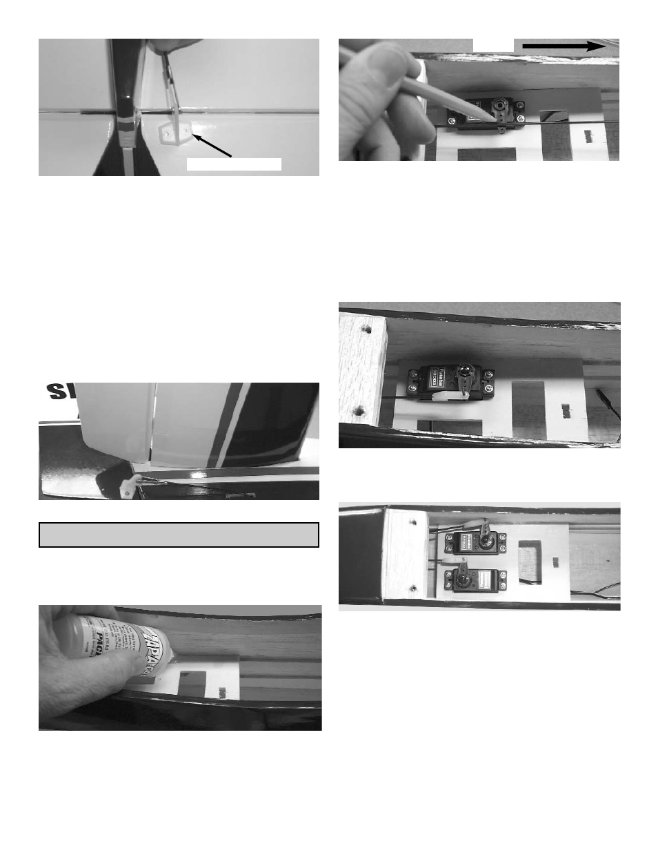
2
.
Glue the servo tray inside the fuselage 3/4”
forward of the rear former in the wing saddle
of the fuselage.
Make sure the side mounted servo hole is
facing forward.
3
.
Tape the elevator so that it stays in the neutral
position.
Mount the elevator servo in the location as
shown above using the screws provided with
the radio.
Align the servo arm so that it is sitting at 90
degrees to the servo.
Mark the location where the elevator pushrod
wire meets the outer hole of the servo arm.
Forward
4.
Bend the wire up 90 degrees at that mark.
Slide the swivel keeper over the end of the
pushrod and snap to the wire.
5.
Repeat steps 1 thru 4 for the rudder servo.