Carl Goldberg GBGA1087 User Manual
Page 14
14
6.
Drill a 1/32” hole in the tail skid mount 1/2” from
the end. Insert the tail skid and cut a slot for the
wire to fit into. Glue in place with medium CA.
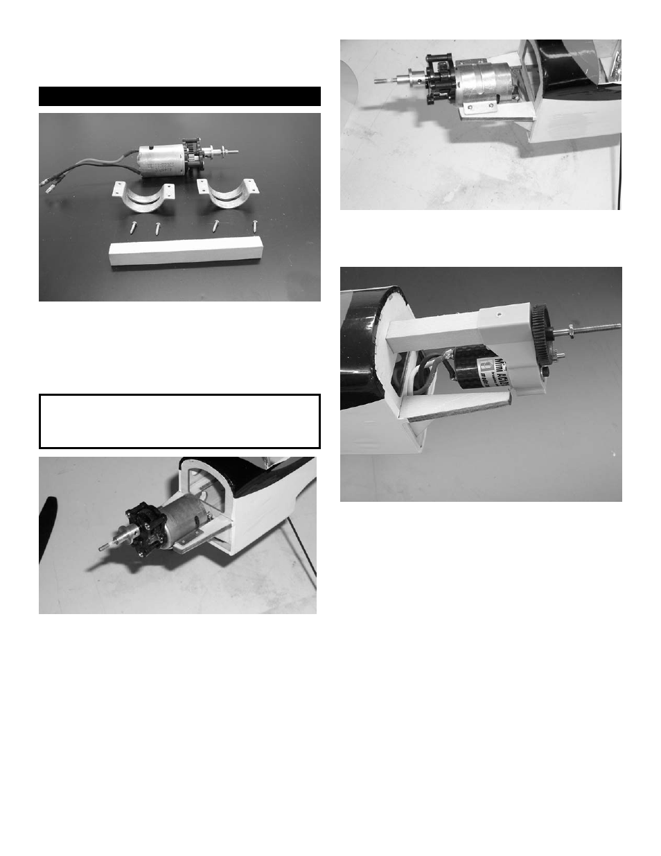
Motor Mount
1.
Collect the following parts:
(1) motor and gear box assembly
(2) motor mounts( clam shell metal)
(4) #2 x 1/2” sheet metal screws
(1) 3/8” square x 3-5/8” spruce motor mount
2.
Set the bottom clam shell mount between the
beams and 1/8” back from the front edge.
Mark the mounting hole location on the beams
and drill a 1/16” hole at each of the 4 spots.
Set the motor in place, pass the wires through
the firewall in the hole provided.
3.
Place the top shell in place and secure using
the four #2x1/2” screws.
4.
An optional motor mount is supplied to mount
the popular beam mount gear drives. Fit the
3/8” square spruce beam in the holes provid-
ed in the firewall and the second bulkhead.
Glue in place with medium CA.
The drive shown is a GWS EP350C with D
gearing (6.6 to 1) It has a Mini AC 1215
brushless motor. This combination mated
with a 2100MAH Li-Poly 3 cell battery and a
12x6 slow fly prop, will give unlimited vertical.
Note:
Motor, motor mounts and gear box shown
for reference only, not included in kit.