Mounting tailwheel, Main landing gear – Carl Goldberg GBGA1090 User Manual
Page 8
8
Collect the following items:
(2) 6-32 x 3” All threaded rod
(2) Small White Adjustable Horn
(1) Tailwheel Bracket
(2) #4 x 1/2” Sheet Metal Screw
(2) #6 Flat Washer
(2) 6-32 Hex Nut
(2) 1/8” Wheel Collars
(2) 4-40 x 1/8 Cup Screw
(2) Tailwheel Springs
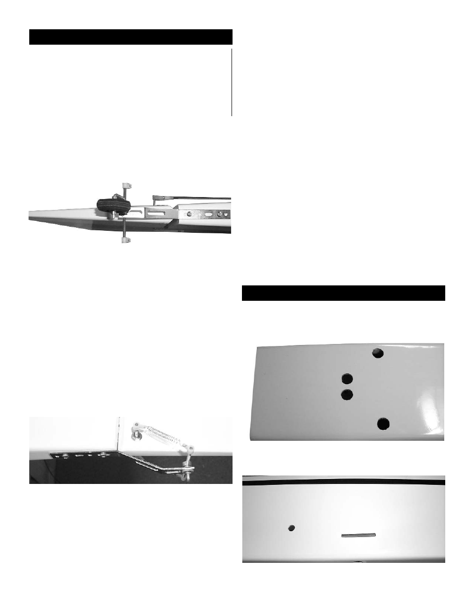
Mounting Tailwheel
1. Mark the center of the fuselage and locate
the tailwheel bracket so the the first bend is on
the rudder hinge line.
2. Mark two hole locations and make two holes
using a 3/32” bit.
3. Mount the bracket to the fuselage using the
#4 x 1/2” sheet metal screws.
4. Thread the 6-32 x 3” rod into brass nob that
is on top of the axle on the bracket.
5. Place on both ends of the threaded rod a
white horn bracket.
6. Drill a 1/8” hole located at 3/4” back from the
hinge line and 1/2” up from the bottom of the
rudder.
7. Insert the second 6-32 x 3” all threaded rod
and center it using the #6 washer with a 6-32
hex nut.
Use thread lock on the nuts.
8.Place on both ends of the threaded rod a
white horn bracket.
9. Connect one side of the spring to the horn
bracket.
10. Then cut the springs to length so that there
is a slight tension in the spring.
11. Connect the springs between the two
adjustable horn brackets.
12. Insert a 4-40 x 1/8” cup screw into each of
the 1/8” wheel collars.
13. Place one of the 1/8” wheel collars onto the
tailwheel bracket axle.
14. Slide the wheel onto the axle and place the
second wheel collar into the axle.
15. Center the wheel on the axle and tighten the
wheel collars next to the wheel.
Main Landing Gear
Collect the following items:
(2) Right & Left Landing Gear
(4) 8-32 x 1/2” Socket Head Bolts
1.Remove the covering over the screw holes for
the main landing gear on the bottom of the fuse-
lage.
2. Remove the covering over the landing gear
slots on the side of the fuselage.