Engine installation, Throttle servo – Carl Goldberg GBGA1090 User Manual
Page 10
10
Engine Installation
Collect the following items:
(2) Nylon Motor mounts
(4) 8-32 x 1” Socket Head Screw
(4) #8 Washer
(4) #8 Lock Washer
(4) #6 x 3/4” Socket Head Sheet Metal Screw
Note:
The firewall is pre-drilled for the motor
mounts. the distance between the motor
mount is 1.915, this will work for the OS 120
FS or the YS 140 or any other motor needing
that clearance.
New blind nuts can easily be installed
in the back of the firewall if your choice of
motor does not fit. Measure between the
screw holes to find the vertical center line.
Locate the horizontal centerline by placing a
motor mount on the firewall and marking the
location that the outer line meets the firewall.
1. Install the motor mounts to the firewall using
the 8-32 x 1” socket head screws and the #8
washers. Use thread Lock on the screws
2. Place your engine on the motor mounts so
that the prop drive washer is 5-3/4” from the
firewall.
3. Mark the motor screw locations and drill a
3/32” hole at each location.
4. Screw the motor to the mounts using the #6 x
3/4” socket head screws.
5. Drill a 3/16” hole at the throttle pushrod loca-
tion.
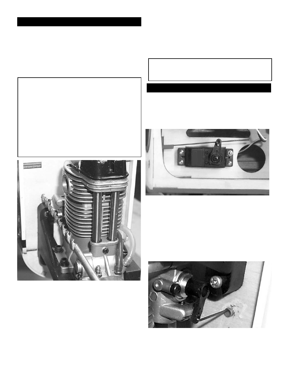
Throttle Servo
Collect the following items:
(1) Throttle Servo with mounting hardware
(1) .062 x 15” Wire
(1) 1/8 x 12” Tubing
1. Install the throttle servo inside the fuselage
using the hardware provided by the radio manu-
facturer.
2. Insert the throttle pushrod tubing through the
firewall and route it back to the throttle servo.
3. Install the EZ connector to the throttle servo
arm. Use Thread Lock
4. Make a bend at one end of the 15” wire.
5. Install the pushrod wire.
Note:
depending on the motor used your pushrod
may not be in the same location as shown.