Rudder servo – Carl Goldberg GBGA1090 User Manual
Page 7
7
Rudder Servo
Collect the following parts:
(1) Servos with mounting screws
(1) 24” Extensions
(1) 4-40 Metal Clevis
(1) 4-40 Hex Nut
(1) Metal Clevis Clips
(1) 4-40 x 6-1/4” Double Threaded Rod
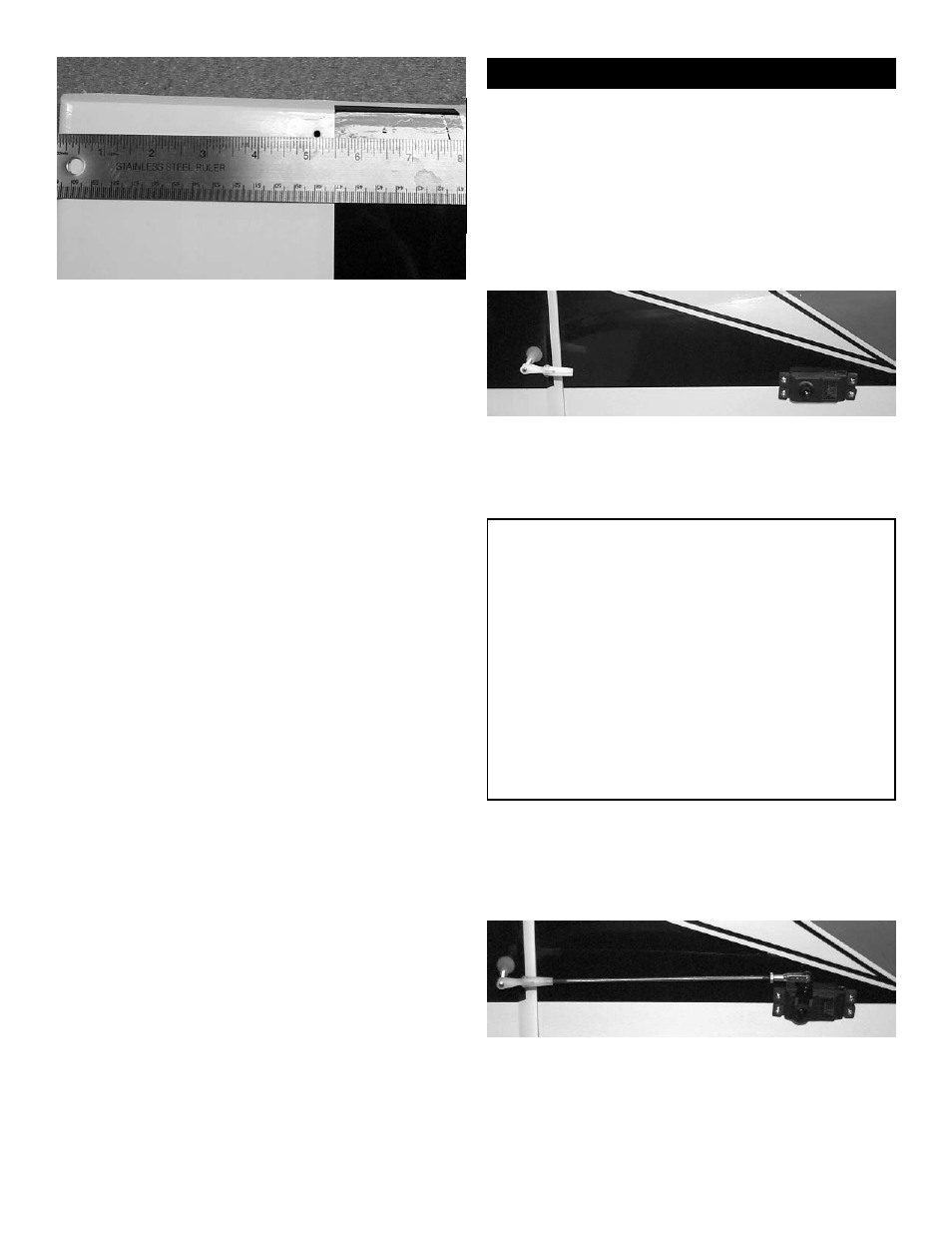
1. Measure up from the bottom of the rudder
approximately 5” to locate the rudder control
horn hole.
2. Using a 1/8” drill, drill half way through the the
hole from both sides till the drill pass through the
rudder.
3. Insert the 6-32 x 2-1/4 allen head bolt into the
left side of the rudder.
4. Thread the bolt all the way till the head is
flush with the side of the rudder.
5. On the side of the rudder, place first the cup
washer then the nylon nut onto the 6-32 bolt.
6. Using a metric allen wrench tighten the nylon
nut all the way down till it rest in the cup washer
and is tight.
7.Thread the nylon adjustable control horn onto
the bolt.(Note: Thread the side that you can
see the cut threads in the nylon onto the
bolt)
8. Hinge the rudder to the fuselage using 3 CA
hinges and thin CA glue.
1. Remove the covering on the right side of the
fuselage over the rudder servo hole. The hole is
just above the elevator hinge line of the stabiliz-
er.
2. Plug the 24” servo extension onto the servo
plug and tape securely.
3. Mount your servo using the hardware sup-
plied with the radio.
Note:
There is a rudder servo hole on both the left
and right side of the fuselage. Using two rud-
der servos will give the rudder more authori-
ty for 3 D aerobatics but, will also place more
weight in the tail, which could cause CG prob-
lems.
If you choose to mount two servos then low
profile servos will probably be need to fit. Or
blocks of wood to move the rudder servos
farther apart inside the fuselage.
We have only supplied to you the hardware
for one servo horn.
4. Connect the pushrod hardware to the rudder
and servo same as you did with the elevators.