Elevator servo, Rudder installation – Carl Goldberg GBGA1090 User Manual
Page 6
6
8. Insert four hinges with pins in the center into
the elevator and slide the elevator on to the cor-
rect stabilizer.
9. Place 3 drops of thin CA on both sides of
each hinge. Remove the pins.
10. Repeat steps 1 thru 9 for the other elevator.
Elevator Servo
Collect the following parts:
(2) Servos with mounting screws
(2) 24” Extensions
(2) 4-40 Metal Clevis
(2) 4-40 Hex Nut
(2) Metal Clevis Clips
(2) 4-40 x 4-1/2” Double Threaded Rod
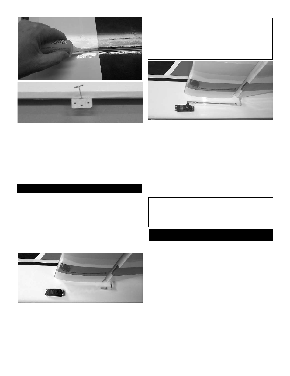
1. Remove the covering over the elevator servo
hole just below the leading edge of the stabilizer.
2. Plug the 24” servo extension onto the servo
plug and tape securely.
3. Mount your servo using the hardware sup-
plied with the radio.
IMPORTANT!
To ensure that any connections located
inside the Fuselage will not come loose,
either when the wires are pulled, or during
flying, always tape them securely together
with electrical tape.
3. Thread the 4-40 x 4-7/8” double threaded rod
into the nylon adjustable control horn.
9. Place a 4-40 hex nut and a metal clevis on
the other end of the threaded rod.
10. Mount the clevis to the servo arm and place
the clevis clip on th clevis.
11. Repeat 1 thru 10 for the second elevator
servo.
Note:
The servo arms that are shown are after mar-
ket arms to help increase the the amount of
servo movement.
Rudder Installation
Collect the following parts:
(1) Rudder
(3) C/A Hinge
(1) Nylon Adjustable Control horn
(1) 6-32 x 2-1/4” Allen head Bolt
(1) Nylon Nut
(1) Nylon Cup Washer