Horizontal and vertical stabilizer construction – Carl Goldberg GPMA0960 Gentle Lady User Manual
Page 5
1. Collect all of the items you will need to construct the HORIZONTAL STABILIZER. They include:
(1) D/C Sheet 6006 (3/16” Balsa) Pt.#3455 (5) TAIL L.E. & T.E. (3/16” X1/4” X21”) PT. #4697
Includes: (1) STAB CENTER (3) TAIL TRUSSES (5/64” X3/16” X24”) PT. #4698
(2) STAB TIPS (1) RUDDER T.E. (3/16” X9/16” X8”) PT.#4701
(1) DORSAL (1) ELEVATOR GUSSETS PT#4696
(1) FIN BOTTOM
2.
Lie the horizontal stabilizer portion of the plan over the
building board and place the waxed paper over the plan.
The main members of the tail assembly are 3/16” x 1/4”
balsa strips. Check to see which strips are the strongest,
and use these for the stabilizer. Lighter ones can be used
in the fin and rudder.
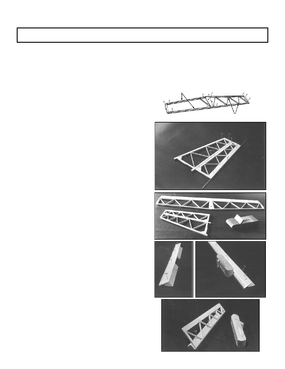
Pin in position and glue at center joint.
Using die-cut stab tips, the center platform and 3/16” x 1/4”
balsa, assemble stab outline.
In cutting the diagonal trusses for the tail, trim them to fit
well. If a bit oversize, don’t force them in place. The
pieces should fit before gluing. It’s better to have them not
meet at the points than to force them in.
Let all parts dry thoroughly.
3.
Assemble fin and rudder in same manner.
Note: Trailing edge of rudder is tapered.-use 1/16” x12” wire
for shim as shown.
Add gussets and let dry throughly.
4.
Temporarily tack-cement elevator to stab, and rudder
to fin (to be removed later). Flat sand parts for uniform
smooth surfaces. Then sand edges, rounding corners and
blending surfaces. Important: Do Not sand the lower
2” of fin L.E. at this time.
Carefully separate elevator and rudder from main units.
5.
Lie the widest side of both 3/4” x 3/4” tri-strips down. Align
strips using a straight edge and separate them by about 3”.
Pin in position.
Position elevator so that its trailing edge rests on top of
tri-strips. Pin elevator in place.
Using a square cornered block, sand front surface of
elevator to match with view on plan.
6.
Pin down 3/4” wide side of one tri-strip. Position rudder so
it rests against angled side of tri-strip. Pin in place.
Sand front surface of rudder to match with view on plan.
5
Horizontal and Vertical Stabilizer Construction
(6 Steps)
Important: This booklet has recently been revised. Therefore, some of the steps in the booklet may not match what is shown
on the plan. Whenever you find such a divergence, follow the instructions in this booklet.
Beveling Rudder
Bevelling Elevator
Gussets
Select strongest pieces for stab L.E. and T.E.
Fit trusses carefully. Don’t force in place.