Carl Goldberg GPMA0960 Gentle Lady User Manual
Page 14
14
14.
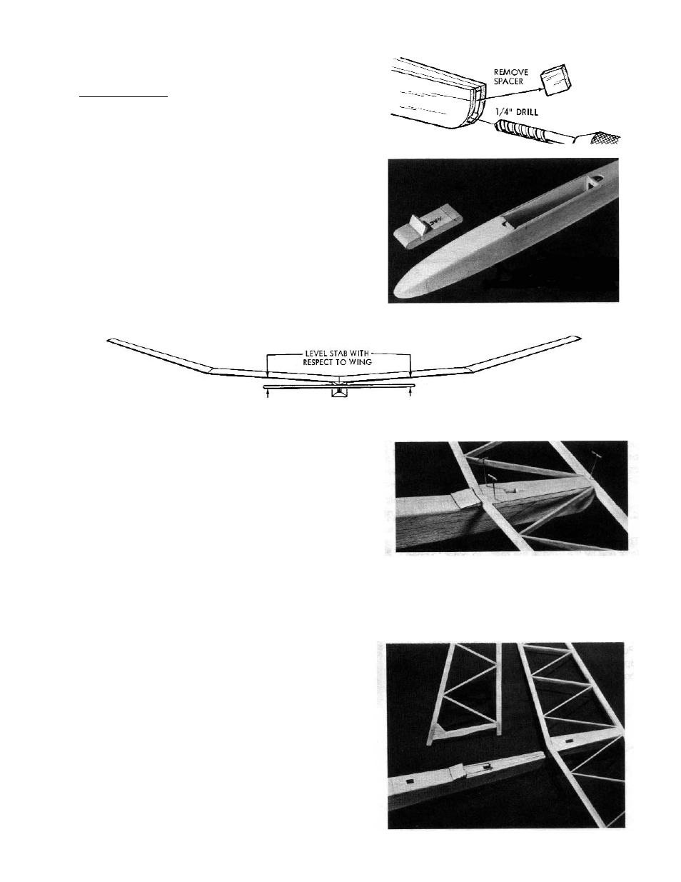
Remove 1/2” square spacer from tail end of fuse.
Carefully drill or carve 1/4” hole at bottom of tail
opening for pushrod exit.
NOTE: AFTER SANDING in Step 13, harden pushrod exit area
using CA.
15.
Carve nose to shape as shown in top and side views.
Install wing, holding it in position with rubber bands.
Trim hatch rear to match wing dihedral, so hatch will be
held down by wing, yet can be slid back under wing 1/4”.
Flat sand hatch, nose and complete fuse. For easier
covering, keep nose flat surfaced, with minimal rounding of
corners. (Caution: excess sanding or trimming of stab
mounting area can alter the incidence angle which has
been die-cut on the fuse sides. Sand this area as little as
possible).
16.
Rubber band wing in place on fuse. Viewing model from
rear, see if stab sets level with respect to wing.
Sand stab platform area as may be necessary to provide a
good level fit for stab. Do not alter pre-set stab incidence
angle (exactly horizontal in side view).
Center stab on fuse using a tape measure to obtain equal
distance from side to side, and from nose to rear corner of
each stab tip. Pin in place. DO NOT GLUE AT THIS
TIME.
From 1/8” scrap make a stab leading edge fairing and glue
in place on fuse. (DO NOT GLUE TO STAB).
17.
With stab centered on fuse, mark through stab center hole.
Remove stab and cut hole in fuse top to receive fin trailing
edge.
Re-position stab on fuse and hold in place with pins. Insert
fin trailing edge in stab center hole. View model from front
and carefully align fin so it points exactly straight ahead.
Pin in position.
Mark location, then cut hole for fin leading edge in fuse top.
*For better under-
standing, see hatch
photo at bottom of
page 14