Carl Goldberg GBGA1069 User Manual
Page 6
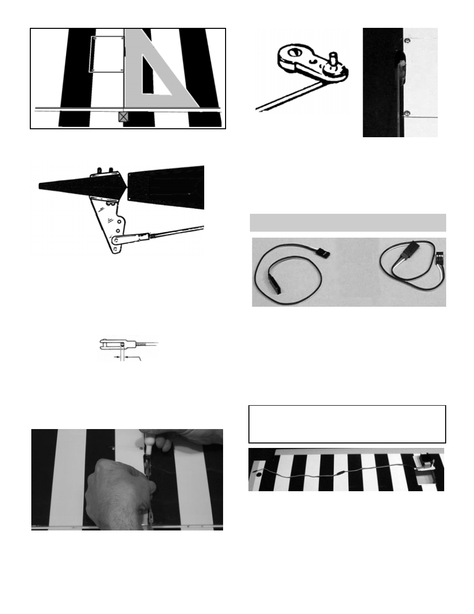
IMPO
RTANT! To ensure that any connections locat-
ed inside the wing will not come loose, either when
the wires are pulled, or during flying, always tape
them securely together with electrical tape.
3.
!
Making sure to use the correct servo for the
opening, attach the servo wire to the 12"
extension and securely tape the connection.
!
Push the extension wire into the tube in the
wing until it comes out the hole near the cen-
ter of the wing.
4.
!
Grasping the extension in the hole, SLOWLY
pull until the end of the 12" extension comes
out of the hole.
2.
!
With the aileron servo door in place, make a
mark at a 90º degree angle to the trailing
edge and in line with the servo arm.
3.
!
Position the control horn so that the snap
link holes are on the mark just made and
right next to the hinge line, as shown.
4.
!
Using a 5/64" drill bit, make a pilot hole in
each screw location.
!
Mount the control horn with the 2-56 x 3/4"
screws.
5.
!
Thread the 1/16 x 7" rod onto the snap link.
Make sure the rod shows in the center of the
snap link.
!
Place the snap link in the second hole from
the top on the control horn.
6.
!
Making sure the aileron is in neutral (level)
position, mark where the wire meets the hole
on the servo arm.
!
Remove the wire and cut it about 1/2"
beyond the mark.
!
Make a 90º bend (or a "z" bend, if preferred)
in the wire and insert the wire in the servo
arm.
6
SERVO EXTENSION INSTALLATION
1.
!
Gather the following items:
(2) 12" Extension wires
(1) Right and left wing halves
2.
!
Remove the servo door and plug one 12"
extension wire into the servo.
!
If the extension is not long enough to reach
to the center of the wing, add an additional
extension to each extension wire for correct
length.
1/16"
!
Secure the wire with a snap nut and then put
a drop of CA glue™ on the snap nut to make
sure it stays in place. Do not glue the snap
nut to the servo arm.