Carl Goldberg GBGA1069 User Manual
Page 14
ELEVATOR PUSHROD INSTALLATION
1.
!
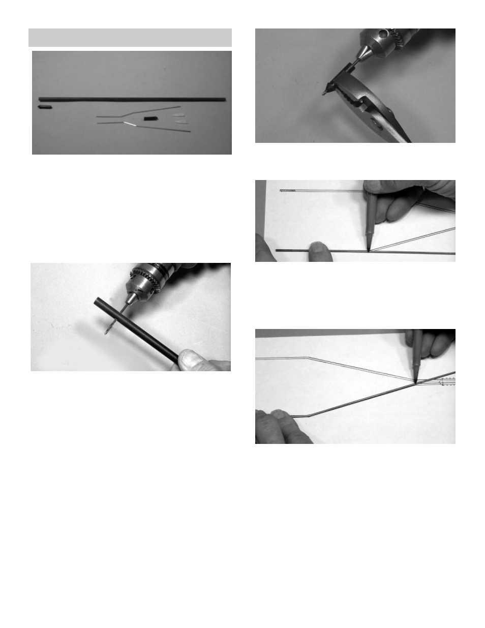
Collect the following items:
(2) .072 x 10” threaded wire
(1) .063 x 6-3/8” wire
(3) Nylon snap link
(1) Single-hole pushrod plug
(1) Double-hole pushrod plug
(1) 36” fiberglass pushrod tube
(2) 1/8 x 24” nylon guide tube
(1) Elevator Wire drawing (Last page in booklet)
2.
!
Using a fine-tooth saw or modeling knife, cut
the fiberglass pushrod to a length of 17-3/4.”
This may be accomplished by rolling the
tube under the blade.
3.
!
Measure 1” back from one end of the
pushrod and drill a 5/64” hole completely
through both sides. This hole will hold the
elevator wires.
4.
!
Measure 1” from the other end of the
pushrod and drill a 5/64” hole HALFWAY
THROUGH the pushrod. TAKE CARE TO
DRILL ONLY THROUGH ONE SIDE.
5.
!
Using the 5/64” drill, and holding a pushrod
plug, as shown, drill out the center of the plug
to form a tube. Repeat for the other plug.
6.
!
Using the Elevator Wire Drawing, place a
threaded 10” wire over Drawing #1, as
shown.
!
Starting at the threaded end, measure back
to the first bend and mark the wire. Then,
carefully bend the wire to match the drawing.
7.
!
Mark the second bend and then bend the
wire accordingly.
!
Repeat this process for a second threaded
wire.
14