Carl Goldberg GBGA1069 User Manual
Page 13
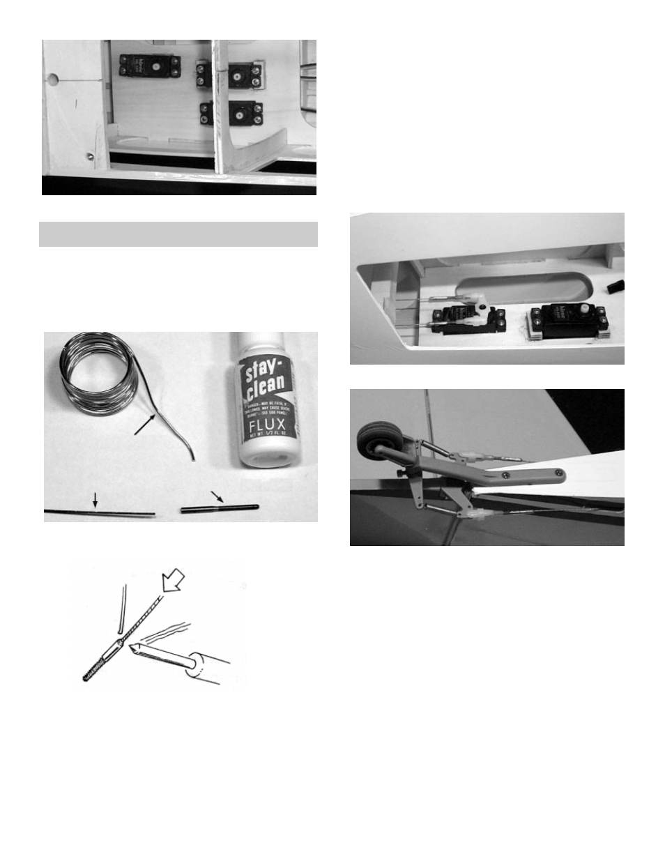
4.
!
Mount the servos as shown above.
Note: To make mounting the rear servo easier, drill a
small hole in the wing mounting block.
1.
!
Collect the following items:
(2) 34” stranded cable
(4) 1/16 threaded couplers
(4) Snap-links
(2) 1/8 x 24” nylon tubing
!
Now, making sure the cable is all the way
into another threaded coupler, solder it to the
cut end. The total length of the finished cable
should be 24”.
!
Repeat the above steps to make a second
cable to the same length.
!
Wash the soldered coupler/cable assembly
with soap and water.
4.
!
Install the cables by using the guide tubing
and threading them through the fuselage, as
was done with the elevator pushrod.
6.
!
Connect two snap links to the center servo,
as shown, and the other two snap links to
the rudder control horn.
!
When the cables are connected test the
tightness by moving the rudder by hand. The
rudder should have very little movement
without moving the servo.
RUDDER CABLE INSTALLATION
2.
!
Using flux and silver solder, solder a thread-
ed coupler onto the end of the cable.
3.
!
From the coupler end, and including the cou-
pler itself, measure 23 inches and mark the
cable. Then cut it with a wire cutter.
5.
!
Place a snap link on each end of each cable.
13