Carl Goldberg GBGA1069 User Manual
Page 18
1.
!
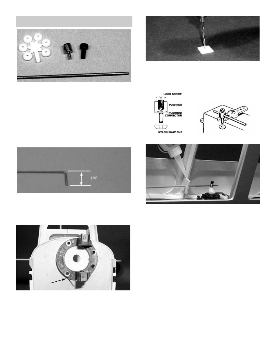
Collect the following items:
(1) .063 x 16-3/4” wire
(1) 1/8 x 24” nylon guide tubing
(1) Snap nut wheel
(1) Pushrod connector
(1) 1/8” x 3/4” x 3/4” plywood tubing support
(1) 4-40 x 1/4” socket head screw
NOTE: The following photos and instructions are for
mounting a 4-cycle engine. Other engines
might require different steps for installations.
THROTTLE PUSHROD INSTALLATION
2.
!
Mark 1/4” from the end of the .063 wire and
make a 90º bend.
3.
!
Cut off a piece of nylon guide tube 12-1/2”
long.
THROTTLE
TUBING
4.
!
Insert the tubing into the hole that you drilled
for the throttle tubing. Push the tubing in to
the fuselage till only 1/8” is sticking out of the
front of the firewall.
5.
!
Drill a 1/8” hole into the plywood pushrod
support.
!
slide the pushrod support on to the end of
the tubing.
6.
!
Install a pushrod connecter onto the throttle
servo arm (see above)
!
Mount the servo arm onto the servo like
shown in the photo above.
!
Insert the .063 wire into the tubing starting at
the firewall.
7.
!
Push the wire into the tubing and guide the
wire into the hole of the pushrod connector.
!
Check that the pushrod moves without bind-
ing. When satisfied then glue support to for-
mer.
!
Glue the pushrod tubing to the firewall land
the tubing support at this time.
Remove the throttle pushrod wire from the
tubing.
18