Fuselage assembly – Carl Goldberg GBGA1069 User Manual
Page 12
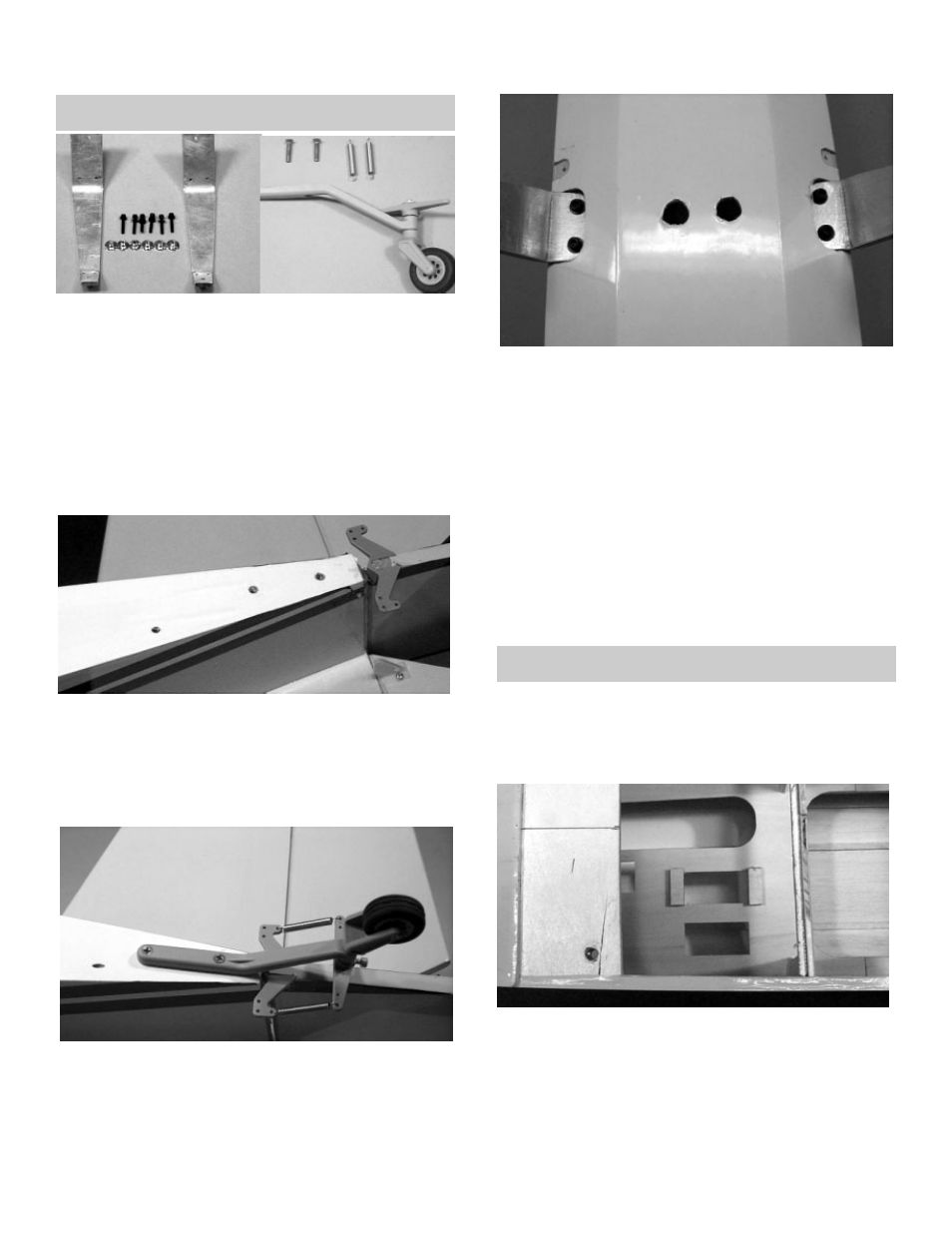
LANDING GEAR INSTALLATION
NOTE: The tailwheel might be different than shown in
your kit.
1.
!
Collect the following parts:
(2) Landing gear
(6) 6-32 x 1/2” Socket Head Screw
(6) #6 Washer
(6) 6-32 Blind Nut
(1) Tail wheel
(2) 4-40 x 1/2” Phillips head screw
(2) Springs
2.
!
Locate the three holes under the covering on
the bottom rear of the fuselage. Remove the
covering from all three holes.
NOTE: The hole nearest to the nose of the model is
the exit hole for the receiver antenna. The other two
holes are for the tailwheel assembly.
3.
!
Mount the tailwheel using the 4-40 x 1/2”
phillips head screws, as shown above. Hook
the springs between the rudder control horn
and the tailwheel bellcrank. It may be neces-
sary to open the end of the springs in order
to connect them to the control horns and the
bellcrank.
4.
!
Working on one landing gear leg at a time,
place the gear in the bottom of the fuselage,
as shown.
!
Align the holes in the landing gear and the
fuselage.
5.
!
Insert a 6-32 x 1/2” socket head screw with a wash-
er into each hole
!
With the screws and the washers through the
gear, reach inside the fuselage and thread on
a 6-32 blind nut.
6.
!
First place a blindnut on each of the screws,
and then tighten down each of them.
!
Repeat for the other side of the landing gear.
FUSELAGE ASSEMBLY
SERVO INSTALLATION
1.
!
Collect the following items:
(2) 1/4 x 3/8 x 1” servo block
(3) Radio servo
(12) Servo mounting screw
2.
!
Test fit to make sure the servos fit snuggly in
the servo tray. Shim or sand, if necessary to
achieve correct fit.
3.
!
Glue the servo blocks at each end of the mid-
dle servo hole.
12