Carl Goldberg GBGA1069 User Manual
Page 16
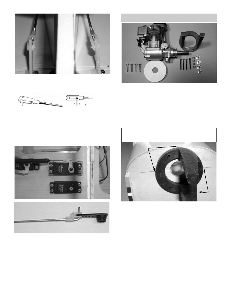
16.
!
Thread the snap-links onto each of the wires,
until the the wire shows in the middle of the
snap-link.
17.
!
Connect the snap-link to the second hole of
control horn.
18.
!
While keeping the elevator level with the
stab, mark where the pushrod wire meets the
servo arm hole.
!
Bend the the pushrod up and cut off the end
of the wire leaving 1/2” up.
!
Slide the snap-r-keeper towards the servo
and snap onto the wire and around the servo
arm.
15.
!
Once the wire has exited the fuselage,
remove the nylon tubing from the end of the
wires.
Motor Mount/Engine Installation
2.
!
Using the alignment marks, center the motor
mount on the firewall and tack glue.
REMEMBER, the following pictures and instruc-
tions may vary slightly, depending on the equipment
you are using.
1 Collect the following items:
(1) Engine
(1) Motor Mount
(4) 6-32 x 1-1/2” socket head screw
(4) 6-32 Blind nut
(4) #6 Washer
(4) #8 x 1” Pan head screw
(3) 1/4” x 2-3/4” Plywood spacer
ALIGN
MARKS
ALIGN
MARKS
16
- GBGQ1296 (12 pages)
- GBGA1079 (25 pages)
- GPMA0963 Cub (33 pages)
- GBGA1023 (12 pages)
- GPMA1956 Eagle 2 ARF (40 pages)
- GPMA0955 EAGLE 2 (59 pages)
- GBGA1080 (9 pages)
- GBGA1046 (21 pages)
- GBGA1045 (21 pages)
- GBGA1040 (16 pages)
- GBGA0040 (40 pages)
- GBGA1082 (10 pages)
- GBGA0055 (44 pages)
- GBGA1041 (20 pages)
- GBGA1070 (17 pages)
- GBGA1078 (23 pages)
- GBGA0050 (26 pages)
- GPMA1940 EP Falcon ARF (16 pages)
- GBGA0057 (60 pages)
- GPMA1960 Gentle Lady Glider ARF (16 pages)
- GPMA0960 Gentle Lady (21 pages)
- GBGA1091 (15 pages)
- GBGA1042 (9 pages)
- GBGA1019 (13 pages)
- GBGA1072 (14 pages)
- GBGA1075 (18 pages)
- GPMP1020 Mini Hold'em Electric Cradle (2 pages)
- GBGP0105 (10 pages)
- GBGA1090 (16 pages)
- GBGA1064 (24 pages)
- GBGA1088 (30 pages)
- GPMA1926 Monster Pitts Electric ARF (17 pages)
- GBGA1058 (9 pages)
- GBGA1087 (16 pages)
- GBGA1092 (24 pages)
- GBGA1085 (19 pages)
- GPMA1993 Skylark 70 Sport ARF (18 pages)
- GPMA1959 Sophisticated Lady Glider ARF (20 pages)
- GBGA0059 (32 pages)
- GPMA1967 Sr. Falcon ARF (21 pages)
- GBGA1089 (19 pages)
- GBGA1067 (19 pages)
- GBGA0067 (39 pages)
- GBGP0108 (4 pages)