Troubleshooting, Wiring diagrams – Braeburn 3200 User Manual
Page 6
10
Rc Rh
Y
Factory Installed
Jumper
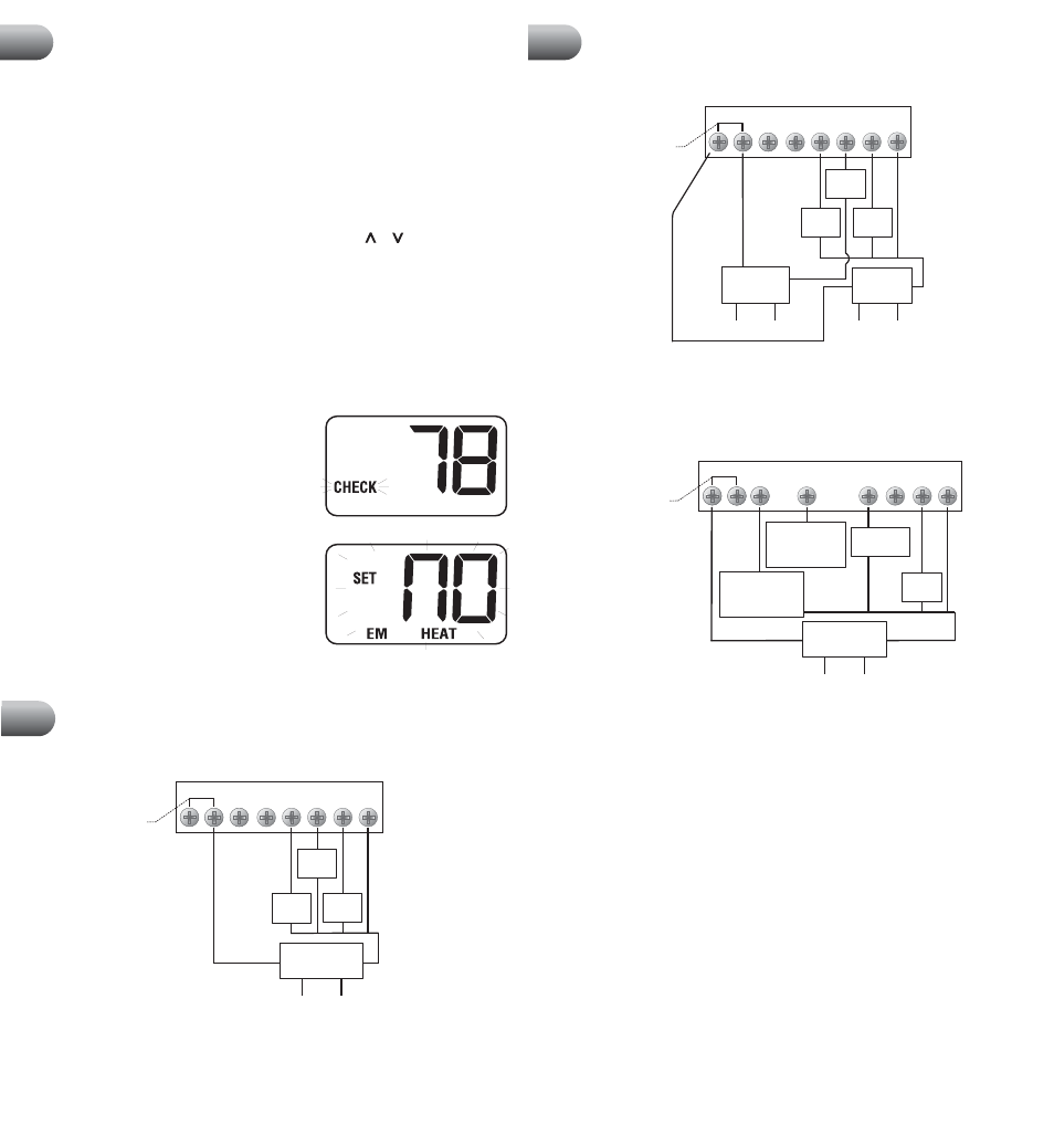
MODEL 3000: Conventional Systems (Single Transformer)
W
G
B
O
24 Volt AC
Transformer
120
Volt AC
Hot Side
Transformer
Rc Rh
Remove
Factory Installed
Jumper
MODEL 3000: Conventional Systems (Dual Transformer)
Cool 24 VAC
Transformer
Heat 24 VAC
Transformer
120
Volt AC
120
Volt AC
Hot Side
Heat
Transformer
Hot Side
Cool
Transformer
Rc Rh
Factory Installed
Jumper
MODEL 3000: Heat Pump Systems
Reversing Valve
(Active in Heating
- See NOTE 2)
Fan
Control
120
Volt AC
Hot Side
Transformer
NOTES:
1. Transformer Common connection not required for battery-only operation
of thermostat. 2. For Heating or Cooling Only system, ignore opposite connection.
3. For 2-wire 24 Volt AC or 250mv - 750mv Millivolt Heating Systems, ignore cooling
connection and fan control.
Troubleshooting
8
cont.
Wiring Diagrams
9
C
Transformer Common
(See NOTE 1)
Y
W
G
B
O
C
Transformer Common
(See NOTE)
NOTE:
Transformer Common connection not required for battery-only
operation of thermostat.
NOTES:
1. Transformer Common connection not required for battery-only operation
of thermostat. 2. For units requiring reversing valve to be energized during heating,
connect reversing valve to B terminal. For units requiring reversing valve to be energized
during cooling, connect reversing valve to O terminal.
Y
W
G
B
O
C
Transformer Common
(See NOTE 1)
Reversing Valve
(Active in Cooling
- See NOTE 2)
Wiring Diagrams
9
cont.
11
Cool
Control
Heat
Control
Fan
Control
Cool
Control
Heat
Control
Fan
Control
24 Volt AC
Transformer
Compressor
Control
Symptom: Cannot program a set point temperature higher than 90˚ F (32˚ C).
Potential Solution: This is above the normal thermostat temperature setting
range of 45˚ to 90˚ F (7˚ to 32˚ C).
Symptom: Cannot program a set point temperature lower than 45˚ F (7˚ C).
Potential Solution: This is below the normal thermostat temperature setting
range of 45˚ to 90˚ F (7˚ to 32˚ C).
Symptom: Thermostat will not allow me to change the set point.
Potential Solution: The keypad is locked. Press either the or key and the
backlight key at the same time to unlock.
Symptom: Fan continues to run all the time whether the system is on or off.
Potential Solution: Check to make sure the fan control switch is in the AUTO
position. This will allow the fan to run only when the heating or cooling system is
turned on and running.
Check thermostat wiring to make sure that the fan control wiring is connected to
the correct terminals on the wiring terminal block. See Section 9.
Symptom: CHECK is shown in thermostat display.
(model 3200 only)
Potential Solution: Switch to emergency heat
if heat is required. Please contact a professional
service technician to verify thermostat and
system performance.
Symptom: NO EM HEAT SET is shown in the
thermostat display. (model 3200 only)
Potential Solution: The thermostat (model 3200
only) is configured for a conventional system,
and the system switch is in the
EM HEAT position.
The unit will still function in a conventional 2
stage
HEAT mode, but the display will flash NO
EM HEAT SET. Move the system switch to the HEAT position.