BASO BGA158 Series CE Approved Class A User Manual
Page 2
2 BGA158 Series CE Approved Class A Shutoff Gas Valve Installation Instructions
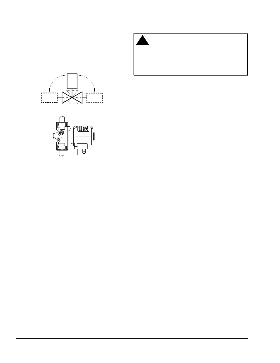
7. The BGA158 valve may be mounted on a
horizontal manifold with the solenoid coils pointed
up (vertical) or in any position not exceeding 90
°
from the vertical. The valve may also be mounted
on a vertical manifold in any position around its
axis (see Figure 1). Do not install the solenoid coil
upside down. Install vertically wherever possible.
90° Maximum
from Vertical
90° Maximum
from Vertical
Limited Horizontal and Vertical
Vertical mounting may be
360º around its axis
with the gas flow either
up or down.
Figure 1: BGA158 Valve Mounting Positions
8. Installer must be a trained, experienced, flame
safeguard control technician. Threads of the pipe
and nipples must be smooth and free of tears and
burrs. Steam clean all piping to remove foreign
substances such as cutting oil or thread chips. A
sediment trap should also be installed in
accordance with the National Fuel Gas Code
NFPA 54 (see Figure 3). Mount the valve to the
pipework, use a quality rated pipe tape, UL listed
seal material rated for gasoline, propane, and
other gases. If not available, a quality grade pipe
dope, a light amount on the male threads, starting
two threads away from the first engageing thread.
If pipe dope lodges on the valve seat, it will
prevent proper closure. Remove excess
compound after mounting the valve to the
pipework.
!
WARNING: Risk of Explosion or Fire.
Verify that there are no gas leaks by testing with
appropriate equipment. Never use a match or lighter
to test for the presence of gas. Failure to test properly
can lead to an explosion or fire and may result in
severe personal injury or death.
9. Check for leakage:
a. Shut off the gas at the main manual shutoff
valve and open the pressure connection
between the manual shutoff valve and the
BGA158 valve.
b. Connect air tubing with a maximum pressure
of 1-1/2 times the valve’s maximum operating
pressure (as indicated on the valve) to the
opened pressure connection.
c. Paint all valve body connections with a rich
soap and water solution.
If bubbles occur, this is an indication of a leak.
To stop a leak, tighten joints and connections.
Replace the part if the leak cannot be stopped.
If bubbles do not occur, remove the air tubing
and close the pressure connection.
10. Make wiring connections. Refer to the Wiring
section for specific wiring instructions.
11. Perform the Checkout section before leaving the
installation.