2 vax matrix and control computer connection, 3 remote control methods and settings – Avlink VAX-2088 User Manual
Page 12
VAX Matrix Switching System—User Manual
11
2.
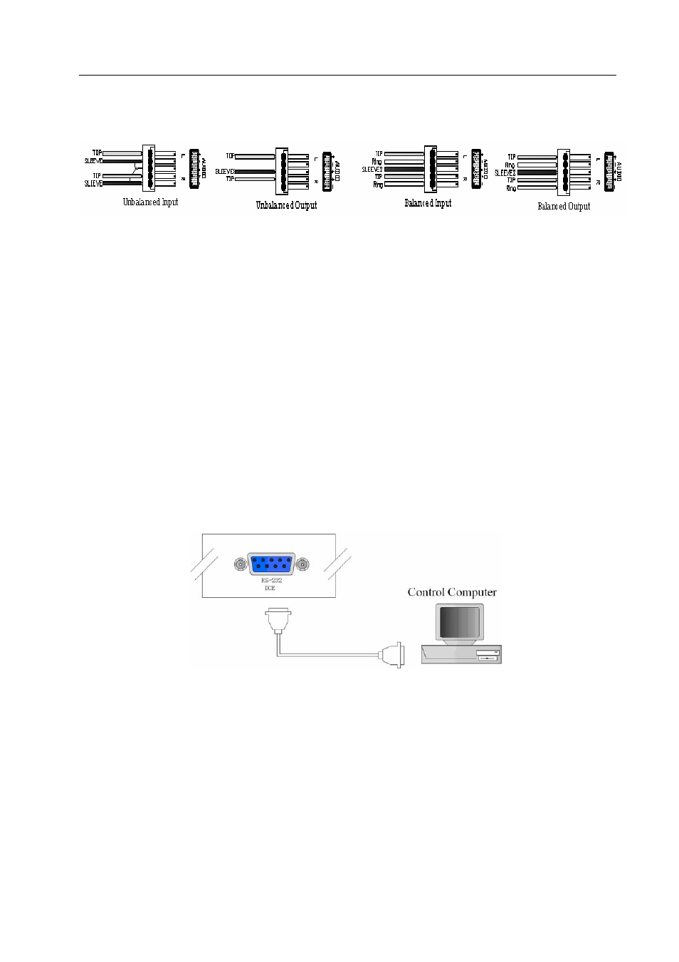
Balanced connection: The “G” leg connects to the Sleeve, and the “-“ leg connects
to the black wire (RING) while the “+” leg connects to the red wire (TIP). Refer to
Figure 5-3 below:
Figure 5-3 5-Phase 3.8mm Audio Connecting Socket Cable(Balanced/Unbalanced
Connection)
To select balanced or unbablanced connection is often depended on the connectors of the
equipment. Use balanced connection as far as possible. Refer to the User Manual prior to
connection. Occasionally, you will have to connect balanced connectors of one piece of
equipment to unbalanced connectors of another equipment. In most cases, you can use
unbalanced connection at the balanced end if quality is not so demanding. If you are demanding
for audio quality, you must use a balun to convert a signal from balanced to unbalanced, or vice
versa.
5.0.2 VAX Matrix and Control Computer Connection
Use the RS-232 connecting cable to connect the computer serial port (COM1 or COM2) to
the RS-232 communication port of the VAX matrix host. The computer can then be used to
control the VAX matrix after installation of application software.
Figure 5-4 VAX Matrix and Computer Connection
5.0.3 Remote Control Methods and Settings
The VAX matrix provides standard RS-232 and RS-485 serial communication ports. Aside
from using the front panel keys for switching operation, you are also permitted to use the RS-232
and RS-485 serial communication ports for remote operation. It also supports RS-485 serial
control.
5.0.3.1 RS-232 Communication Port, Connection Methods
The RS-232 port is a 9-pin female connector. The Leg functions are shown in the table
below: