Safety device testing – AERCO BMK 3.0 LN Nat. Gas Jan 2009 User Manual
Page 48
SAFETY DEVICE TESTING
6-4
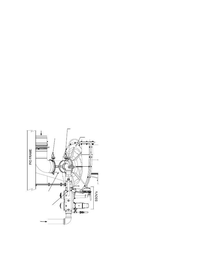
3. Close the manual gas shutoff valve located
between the Safety Shut-Off Valve (SSOV)
and the Air/Fuel Valve (see Figure 6-3).
4. Set
the
ON/OFF switch to the ON position to
start the unit.
5. The unit should shut down after reaching the
Ignition cycle and display FLAME LOSS
DURING IGN.
6. Open the valve previously closed in step 3
and press the CLEAR button.
7. Restart the unit and allow it to prove flame.
8. Once flame is proven, close the manual gas
valve located between the SSOV and the
Air/Fuel Valve.
9. The unit should shut down and display
FLAME LOSS DURING RUN.
10. Open the valve previously closed in step 8.
11. Press the CLEAR button. The unit should
restart and fire.
MANUAL GAS
SHUTOFF
VALVE
HANDLE
AIR
INLET
AIR/FUEL
VALVE
BLOWER
GAS
INLET
PARTIAL LEFT SIDE VIEW
BLOCKED
INLET
SWITCH
BLOWER PROOF
SWITCH
Figure 6-3
Manual Gas Shut-Off Valve Location
6.8 AIR FLOW FAULT TESTS
These tests check the operation of the Blower
Proof Switch and Blocked Inlet Switch shown in
Figure 6-3.
1. Start the unit in the Manual Mode at a firing
rate between 25% and 30%.
2. Once the unit has proved flame, remove the
memory stick from the Variable Frequency
Drive (VFD).
3. The Blower Proof Switch will open and the
blower should stop. The unit should shut
down and display AIRFLOW FAULT
DURING RUN.
4. Replace the memory stick in the VFD.
5.
Press the CLEAR button. The unit should
restart.
6. Next, check the Blocked Inlet Switch by
closing the Iris Air Damper to position 8.
7. .The unit should shut down and again
display AIRFLOW FAULT DURING RUN.
8. Return the Iris Air Damper to its previous
setting.
9. Press the CLEAR button. The unit should
restart.
6.9 SSOV PROOF OF CLOSURE SWITCH
The downstream SSOV (#1) shown in Figure
6-1 contains the proof of closure switch. The
proof of closure switch circuit is checked as
follows:
1. Set the unit’s ON/OFF switch to the OFF
position.
2. Place the unit in Manual Mode and set the
firing rate between 25% and 30%
3. Refer to Figure 6-1 and locate downstream
SSOV #1.
4. Remove the cover from SSOV #1 by
loosening the screw shown in Figure 6-4. Lift
off the cover to access the terminal wiring
connections.
5. Disconnect wire #148 from SSOV #1 to
“open” the proof of closure switch circuit.
6. The unit should fault and display SSOV
SWITCH OPEN.
7. Replace wire #148 and press the CLEAR
button.