Appendix k – AERCO BMK 3.0 LN Nat. Gas Jan 2009 User Manual
Page 116
APPENDIX K
K-2
K-1. NATURAL GAS COMBUSTION
CALIBRATION
The combustion calibration procedures provided
in this Appendix apply only to Benchmark 3.0LN
units with serial numbers below G-07-1901.
All Benchmark 3.0LN Boilers are combustion
calibrated at the factory prior to shipping.
However, recalibration as part of initial start-up
is necessary due to changes in the local altitude,
gas BTU content, gas supply piping and supply
regulators. Factory Test Data sheets are
shipped with each unit. These sheets must be
filled out and returned to AERCO for proper
Warranty Validation.
It is important to perform the following procedure
as outlined. This will keep readjustments to a
minimum and provide optimum performance.
1. Open the water supply and return valves to
the unit and ensure that the system pumps
are running.
2. Open the natural gas supply valve(s) to the
unit.
3. Set the control panel ON/OFF switch to the
OFF position.
4. Turn on external AC power to the unit. The
display will show LOSS OF POWER and the
time and date.
5. Set the unit to the Manual Mode by pressing
the AUTO/MAN key. A flashing Manual Fire
Rate message will be displayed with the
present rate in %. Also, the MANUAL LED
will light.
6. Adjust the fire rate to 0% by pressing the ▼
arrow key.
7. Ensure that the leak detection ball valve
down-stream of SSOV No. 2 is open.
8. Set
the
ON/OFF switch to the ON position.
9. Change the fire rate to 29% using the ▲
arrow key. The unit should begin its start
sequence and fire.
10.
Next, verify that the gas pressure
downstream of SSOV No. 1 is 1.5” W.C. for
both FM and IRI gas trains. If gas pressure
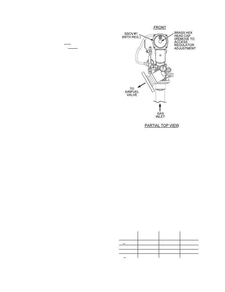
adjustment is required, remove the brass
hex nut on downstream SSOV No. 1
containing the gas pressure regulator
(Figure K-1). Make gas regulator adjust-
ments using a flat-tip screwdriver to obtain
1.5” W.C.
Figure K-1
Regulator Adjustment Screw Location
11. Raise the firing rate to 100% and verify that
the gas pressure downstream of SSOV No.
1 remains at 1.5” W.C. Readjust pressure if
necessary.
12. With the firing rate at 100%, insert the
combustion analyzer probe into the flue
probe opening and allow enough time for the
combustion analyzer to settle.
13. Compare the measured oxygen level to the
oxygen range for the inlet air temperature
shown in Table K-1. Also, ensure that the
carbon monoxide (CO) and nitrogen oxide
(NOx) readings do not exceed the values
shown.
Table K-1
Combustion Oxygen Levels for a 100%
Firing Rate
Inlet Air
Temp
Oxygen %
± 0.2
Carbon
Monoxide
NOx
>100°F
4.8 %
<100 ppm
<30 ppm
90°F
5.0 %
<100 ppm
<30 ppm
80°F
5.2 %
<100 ppm
<30 ppm
<70°F
5.3 %
<100 ppm
<30 ppm