3 operation of line server model 305 – Kofax Communication Server 10.0.0 User Manual
Page 96
Environment Guide
Version 10.00.00
96
© Copyright Kofax. All information is subject to change without notice.
Unavailable time 1:52.
8.1.3
Operation of Line Server Model 305
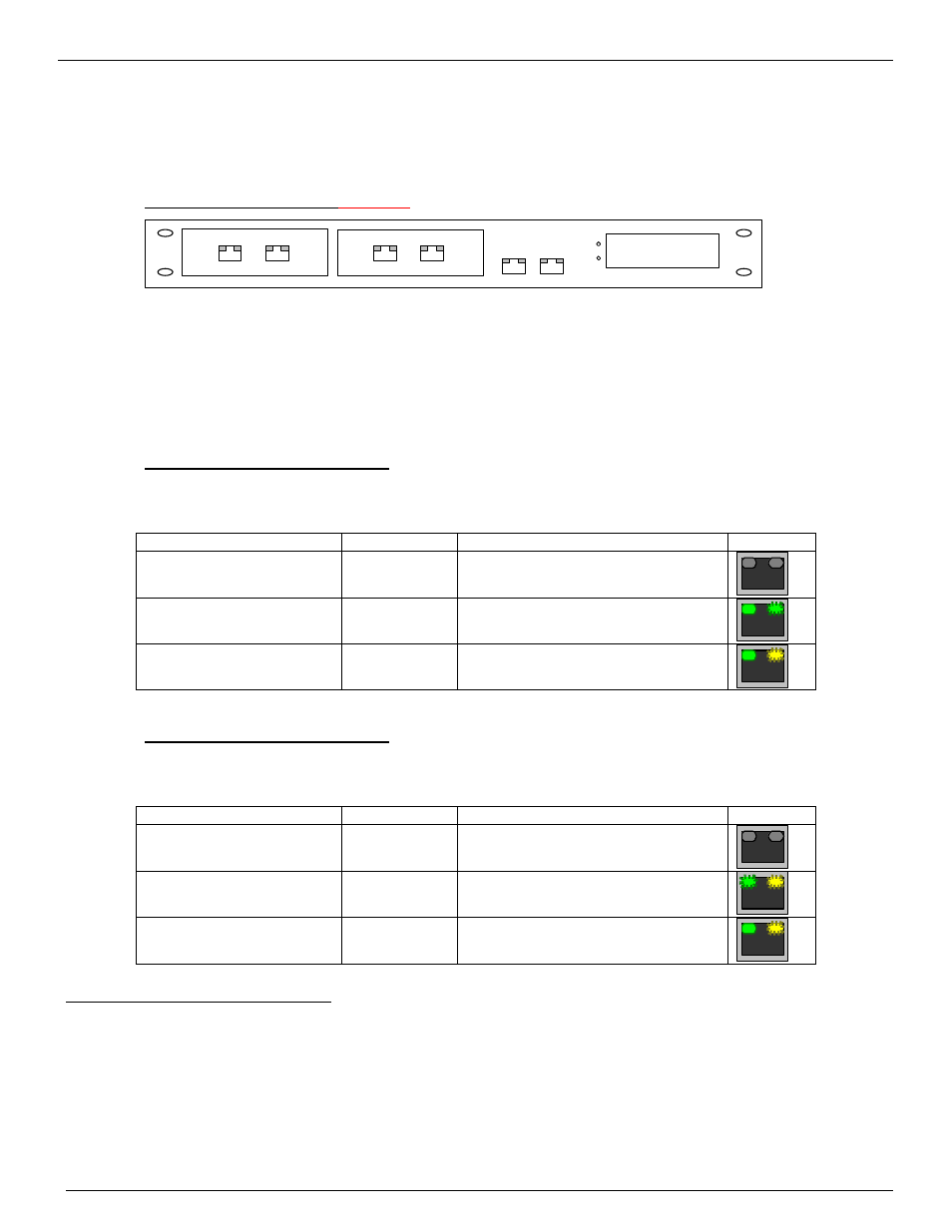
Front View of L
INE
S
ERVER
Model 305
16x2 character
LC-Display
Mode
Set
LAN 2
LAN 1
PRI 1
PRI 2
BRI 1
BRI 2
On the front side of L
INE
S
ERVER
Model 305
there are connectors to BRI/PRI and LAN lines. Each plug has
2 LEDs that indicate Status and Activity as shown in the tables below. Please note that there are slight
differences between the LEDs of LS1V1 and those of LS1V2. General Status information (version, IP
address and heartbeat) is shown on a LCD. 2 buttons are provided to reset the L
INE
S
ERVER
Model 305
and
to setup IP-Addresses.
Find a description of Front side controls also in the Line Server Model 305 Manual!
Description of LAN LEDs on LS1V1
The LS1V1 is the old Line Server Model 305. It contains a TC16 main board and up to four TC22 modules
with a DSP processing power.
Connection
Left LED
Right LED
Example
no LAN signal detected
off
off
10 Mbps LAN connection
steadily green
flickering green to indicate activity
on LAN
100 Mbps LAN connection
steadily green
flickering yellow to indicate activity
on LAN
Description of LAN LEDs on LS1V2
The LS1V2 is the new generation of the Line Server Model 305. It contains a TC18 main board that already
includes the DSP processing power.
Connection
Left LED
Right LED
Example
no LAN signal detected
off
off
10 Mbps LAN connection
blinking green
1 sec on/off
flickering yellow to indicate activity
on LAN
100 Mbps LAN connection
steadily green
flickering yellow to indicate activity
on LAN
Description of TC23/TC24/TC26 LEDs