Wiring, Method of operation, Specificatons – KEYENCE CA-U4 User Manual
Page 2: Output derating characteristics, Dimensions, Terminals crimp terminals cables
- 2 -
Wiring
Terminals
Crimp terminals
Cables
Select cables with a wire diameter suited to the output rated current.
Method of Operation
The display mode changes each time when the MODE switch is pressed.
• The CA-U4 is set to the output current display mode before shipment. It retains the
display mode that was used before the power was turned off.
• The maximum value for the peak current display mode is cleared when the power is
turned off and the display mode is changed.
• When the switch is held down for 3 seconds or more, the current mode is locked and cannot
be changed. To unlock the mode, hold down the switch again for 3 seconds or more.
Specificatons
*1 For conforming to safety standards shown above, rated input voltage is 100 to 240 VAC 50/60 Hz.
*2 To reset the unit, turn off the input power once, wait for 1 minute or more, and then turn on the input power again.
*3 The Applicable standards do not apply for parallel and serial operations.
Output Derating Characteristics
* The characteristic data shown above are obtained when this unit is installed as described in this Manual.
* The surrounding air temperature is the temperature 50 mm below the bottom of the unit.
Dimensions
Screw size
Tightening torque
M4
1.2 N·m
Model
CA-U4
Input
conditons
Rated Input voltage
*1
100 to 240 VAC (85 to 264 VAC, 110 to 370 VDC)
Rated Frequency
*1
50/60 Hz (47 to 63 Hz, DC)
Input current (100/200 VAC)
2.2 A/1.1 A max.
Efficiency (100/200 VAC)
82%/85% typ. (with 100% load)
Leakage current (100/200 VAC) 0.4 mA/0.75 mA max. (with 100% load)
Rush current (100/200 VAC)
25 A/50 A max. (with 100% load, at 25 ºC cold start)
Output
conditons
Rated output voltage
24V DC
Adjustable voltage range
5% (with V.ADJ)
Rated output current
6.5 A
Ripple/noise voltage
180mVp-p max.
Input fluctuation
0.4 % max.
Load fluctuation
1.5 % max.
Temperature fluctuation
0.02 %/ºC max.
Starting time
500 ms max.
(at Surrounding Air Temperature of 0 to 55ºC under rated I/O conditions)
Output holding time
20 ms min. (at Surrounding Air Temperature of 25ºC under rated I/O conditions)
Protection
Overcurrent protection
Constant current voltage limiting. Automatic reset
7.9 A min.
Overvoltage protection
*2
Activates when the voltage reaches 26.4 V or more. Voltage turn-off.
Operation resumes when the input power is turned on again.
Display
Display method
3-digit, 7-segment LED (Character height: 10 mm)
Memory backup time
Approx. 10 years (at 20ºC)
Display resolution
0.1 A/0.1 V/1%
Environment
Surrouding Air Temperature
(for operation)
–10 to 55ºC, No condensation (See "Output Derating Characteristics".)
Relative humidity
25 to 85%, No condensation
Surrounding Air Temperature
(for storage)
–20 to 70ºC, No condensation
Withstand voltage
3.0 kVAC 50/60 Hz 1 min (across input and output terminals),
2.0 kVAC 50/60 Hz 1min (across input terminals and PE terminal)
500 VAC 50/60 Hz 1 min (across output terminals and PE terminal)
Shock
Peak acceleration: 300 m/s
2
, in X, Y, and Z directions, 2 times respectively
Vibration
In X, Y, and Z directions, 2 hours respectively under the following conditions
10 to 57 Hz, 0.3 mm double-amplitude, 57 to 500 Hz, 19.6 m/s
2
(2G), 5.5-minute cycle
Insulation resistance
100 M
min. (with 500 VDC megohmmeter) (across input and output terminals)
(across input terminals and PE terminal) across output terminals and PE terminal)
Applicable
standard
Safety standard
UL : UL508, UL60950-1
C-UL : CSA C22.2 No.14-M95, CSA C22.2 No.60950-1-03
EN : EN60950-1, EN50178
IEC : IEC60950-1
EMC standard
FCC Part15B ClassA, EN55011 ClassA, EN61000-6-2
Limits for harmonic current
emissions
EN61000-3-2
Other
Parallel operation
Possible (OP-42207 is required.)
*3
Serial operation
Possible (External diode is required.)
*3
Cooling method
Natural air-cooling
Weight
Approx. 700g
8.0 mm max.
8.0 mm max.
M4 size
M4 size
.3.
0.7
Output current
display
Load factor
display
Peak current
display
Output voltage
display
Displays the output current down to 0.1 A.
Displays the load factor down to 1%.
When the load factor is over 100% , displays "FFP".
Displays the maximum value of the output current down to
0.1 A. The current and "PH" are displayed alternately.
Displays the output voltage down to 0.1 V.
.
3
.
5
.
P
.3.
1.3
.
2
.
4.0
Load factor (%)
100
90
80
70
60
50
40
30
20
10
0
-10
0
10
20
30
40
50
70
60
Surrounding air temperature (°C)
WARRANTIES AND DISCLAIMERS : KEYENCE, at its sole option, will refund,
repair or replace at no charge any defective Products within 1 year from the date
of shipment. Unless stated otherwise herein, the Products should not be used
internally in humans, for human transportation, as safety devices or fail-safe
systems. EXCEPT FOR THE FOREGOING, ALL EXPRESS, IMPLIED AND
STATUTORY WARRANTIES, INCLUDING WARRANTIES OF
MERCHANTABILITY, FITNESS FOR A PARTICULAR PURPOSE AND
NONINFRINGEMENT OF PROPRIETARY RIGHTS, ARE EXPRESSLY
DISCLAIMED. KEYENCE SHALL NOT BE LIABLE FOR ANY DIRECT,
INDIRECT, INCIDENTAL, CONSEQUENTIAL OR OTHER DAMAGES, EVEN IF
DAMAGES RESULT FROM THE USE OF THE PRODUCTS IN ACCORDANCE
WITH ANY SUGGESTIONS OR INFORMATION PROVIDED BY KEYENCE. In
some jurisdictions, some of the foregoing warranty disclaimers or damage
limitations may not apply.
E1101-3
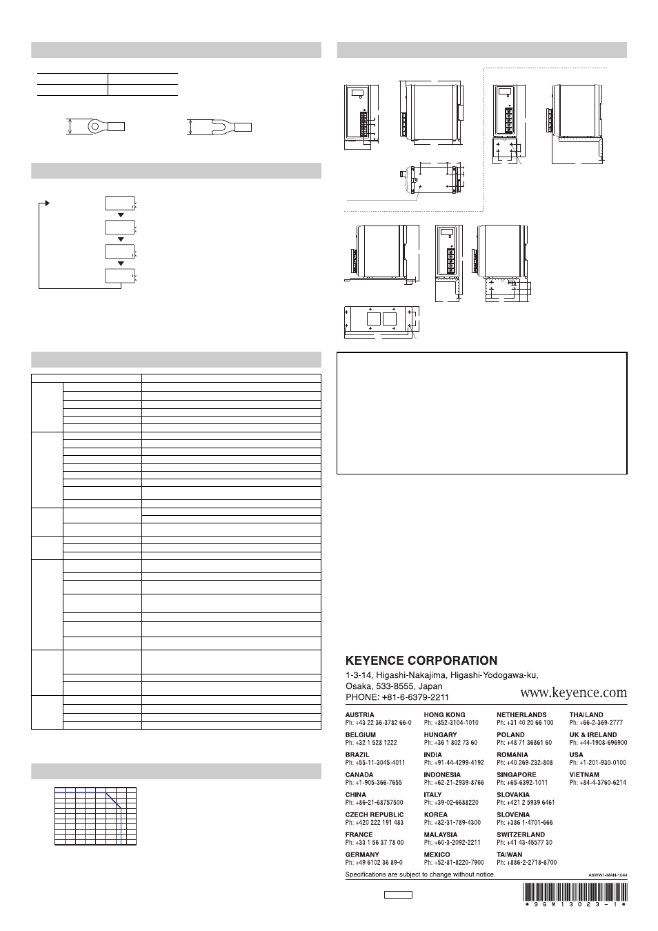
The side mounting bracket can be attached to either sides.
When front mounted
(Mounting bracket : OP-42174)
When side mounted
(Mounting bracket : OP-51629)
10
14.3
122.5
2.5
16.1
(12)
120
85.5
16.5
60
28
28
15.5
4-M3 Screw insertion depth 5 max.
Screw hole for mounting
40
170
12.5
15
122
t=2
59
12.5
7
15
20.5
75
50
12.5
157
60
t=2
When bottom mounted
(Mounting bracket : OP-42175)
160
150
55
40
132.5
t=2
12.5
4-5
4-5
59
43.3
35.9
5
Copyright (c) 2014 KEYENCE CORPORATION. All rights reserved.
13023E 1054-1 96M13023 Printed in Japan